
Air conditioner indoor unit

A technology for an indoor unit and a casing of an air conditioner is applied in the field of air conditioners, which can solve the problems of accelerating the failure of electrical components in an electric control box, affecting the reliability of the indoor unit of the air conditioner, and the failure of the wire body, so as to save assembly space and improve stable operation. The effect of reducing the amount of oil smoke

Active Publication Date: 2021-03-16
GD MIDEA HEATING & VENTILATING EQUIP CO LTD +1
View PDF8 Cites 0 Cited by
  • Summary
  • Abstract
  • Description
  • Claims
  • Application Information

AI Technical Summary

Problems solved by technology

Due to the relatively large amount of oily fumes in the kitchen, the oily fumes can gather on the wires of the indoor unit of the air conditioner, and a large amount of oily fumes will cause the wires to fail and leak.
Moreover, oil fume can also enter the electric control box through the wire hole on the electric control box, thereby accelerating the failure of the electrical components in the electric control box and affecting the reliability of the air conditioner indoor unit.

Method used


Image

  • Air conditioner indoor unit
  • Air conditioner indoor unit
  • Air conditioner indoor unit

Examples


Embodiment Construction

[0035] Embodiments of the present invention are described in detail below, examples of which are shown in the drawings, wherein the same or similar reference numerals designate the same or similar elements or elements having the same or similar functions throughout. The embodiments described below by referring to the figures are exemplary only for explaining the present invention and should not be construed as limiting the present invention.

[0036] In describing the present invention, it is to be understood that the terms "length", "width", "thickness", "upper", "lower", "vertical", "horizontal", "top", "bottom", The orientation or positional relationship indicated by "inner", "outer", etc. is based on the orientation or positional relationship shown in the drawings, and is only for the convenience of describing the present invention and simplifying the description, rather than indicating or implying that the referred device or element must have Certain orientations, constru...


PUM


Abstract

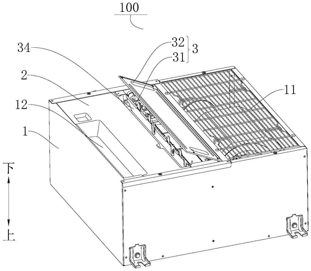
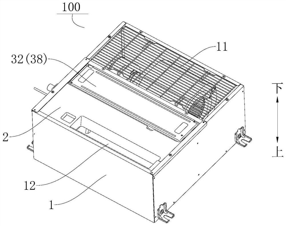
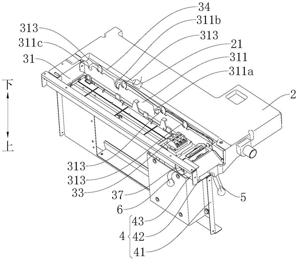
The invention discloses an air conditioner indoor unit. The air conditioner indoor unit comprises a machine shell, a water receiving tray and an electric control box. A heat exchanger and a motor arearranged in the machine shell, and the water receiving tray is arranged in the machine shell and located below the heat exchanger. The electric control box comprises a box body, a box cover and an electric control component. A first line-passing cavity is defined between the line-passing side wall of the box body and the water receiving tray, and a second line-passing cavity is defined between thetop wall of the box body and the water receiving tray. The first line-passing cavity communicates with the second line-passing cavity, and line-passing holes are formed in the second line-passing cavity. Containing space is formed in the box body, and wire inlet openings communicating with the containing space are formed in the line-passing side wall. The box cover is arranged at the bottom of the containing space to cover the containing space. According to the air conditioner indoor unit, through the arrangement of the first line-passing cavity and the second line-passing cavity, the distribution and installation of line bodies are facilitated, and centralized placement of the line bodies and assembly space saving are realized. When the air conditioner indoor unit is installed in a kitchen, oil smoke proof can be realized, so that the damage of oil smoke to the electronic control component and the line bodies is reduced.

Description

technical field [0001] The invention relates to the technical field of air conditioners, in particular to an air conditioner indoor unit. Background technique [0002] In the related art, an air conditioner indoor unit may be installed in a kitchen. Due to the relatively large amount of oily fumes in the kitchen, the oily fumes can gather on the wires of the indoor unit of the air conditioner, and a large amount of oily fumes will cause the wires to fail and leak. Moreover, oil fumes can also enter the electric control box through the wire hole on the electric control box, thereby accelerating the failure of the electrical components in the electric control box and affecting the reliability of the air conditioner indoor unit. Contents of the invention [0003] The present invention aims to solve at least one of the technical problems existing in the prior art. For this reason, the present invention proposes an air-conditioning indoor unit, which has the advantages of rea...

Claims


Application Information

Patent Timeline
Patent Type & Authority Patents(China)
IPC IPC(8): F24F1/0063F24F13/00F24F13/22
CPCF24F1/0003F24F13/00F24F13/222
Inventor 谷勇李艳荣黄笛张文武唐华彬李健锋姚嘉
Owner GD MIDEA HEATING & VENTILATING EQUIP CO LTD
Learn More