Manufacturing method of charging coil stamping

A manufacturing method and charging coil technology, applied in coil manufacturing, transformer/inductor coil/winding/connection, circuit, etc., can solve the problems of easy pollution, complicated manufacturing method, large gap between charging coils, etc.

Active Publication Date: 2019-06-11
DONGGUAN LINGYI PRECISION MFG TECH CO LTD
View PDF1 Cites 0 Cited by
  • Summary
  • Abstract
  • Description
  • Claims
  • Application Information

AI Technical Summary

Problems solved by technology

However, this method still has shortcomings, the manufacturing method is very complicated, the operation of electroless copper plating or electroless copper plating is complicated, and it is easy to cause pollution
At the same time, the helical coil slot and feed point slot must have a certain wall thickness, resulting in a large gap between the charging coils, and the charging efficiency of the final product is not high.

Method used


Image

  • Manufacturing method of charging coil stamping
  • Manufacturing method of charging coil stamping
  • Manufacturing method of charging coil stamping

Examples


Embodiment Construction

[0040] Attached below Figures 1 to 11 The present invention is described in further detail.

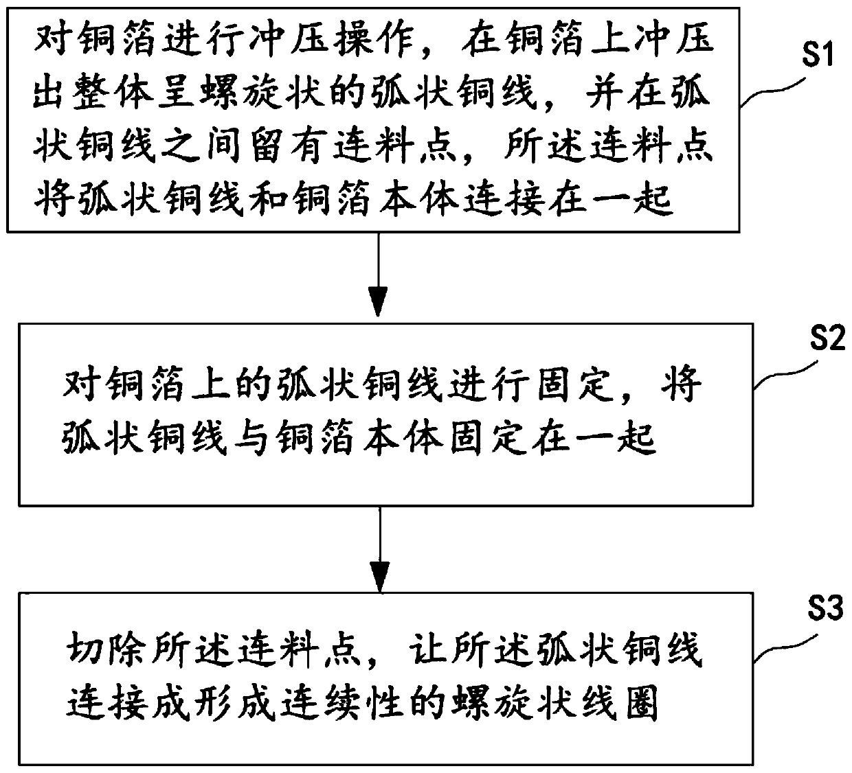
[0041] The invention discloses a charging coil stamping manufacturing method, which includes the following steps:

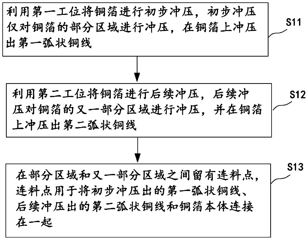
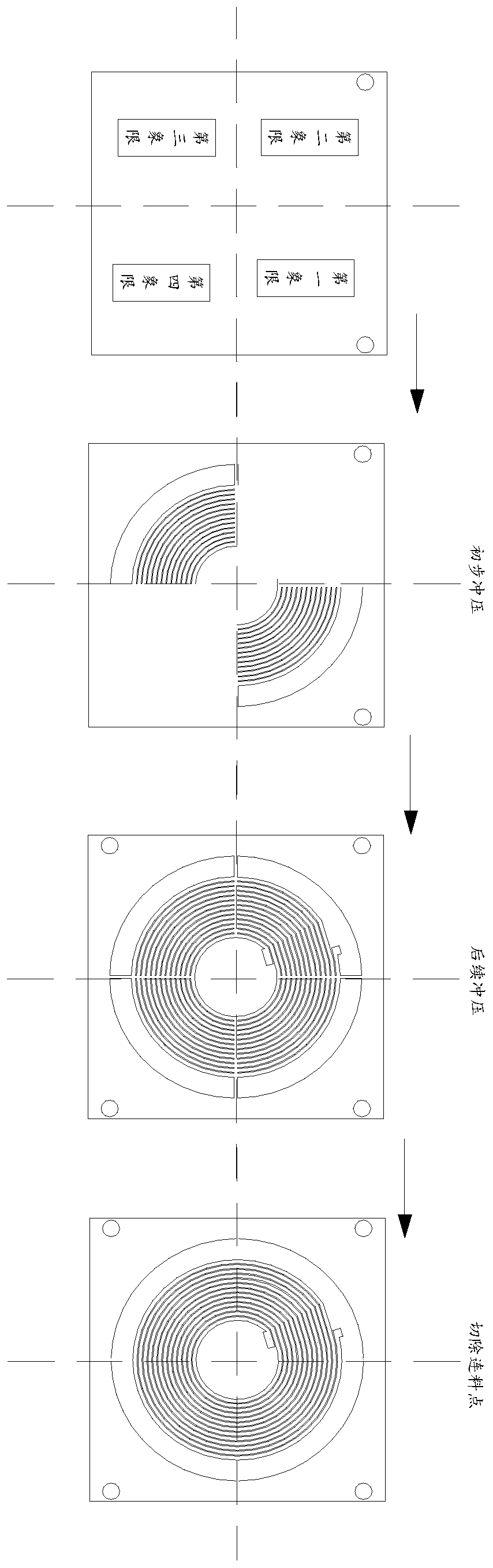
[0042] Step S1: Stamping the copper foil, stamping out the overall spiral arc-shaped copper wire on the copper foil, and leaving a connecting point 201 between the arc-shaped copper wires, the connecting point 201 connects the arc-shaped copper wire and the copper foil the bodies 204 are connected together;

[0043] Step S2: Fix the arc-shaped copper wire on the copper foil, and fix the arc-shaped copper wire and the copper foil body 204 together;

[0044] Step S3: cutting off the connecting point 201, and connecting the arc-shaped copper wires to form a continuous helical coil.

[0045] After the punching operation, a part area will be reserved, that is, there will be a connecting point 201 between the arc-shaped copper wires. The connecting point 201 is used to con...


PUM


Abstract

The invention discloses a method for manufacturing a charging coil. The method comprises the following steps of: carrying out stamping operation on a copper foil, punching an arc-shaped copper wire with a spiral shape on the copper foil, and reserving a connecting material point between the arc-shaped copper wires, and connecting the arc-shaped copper wire and the copper foil body together; fixingthe arc-shaped copper wire on the copper foil, and fixing the arc-shaped copper wire and the copper foil body together; and cutting the connecting material points so that the arc-shaped copper wiresare connected to form a continuous spiral coil. The beneficial effect is that after the punching operation, the connecting point is left between the curved copper wires, and the connecting point is used to connect the arc-shaped copper wire with the copper foil body, thereby preventing the arc-shaped copper wire from prolapsed in a state in which the copper foil is suspended. Before the connectingpoint is cut off, the arc-shaped copper wire on the copper foil is fixed without prolapse. After the connecting point is cut off, the arc-shaped copper wire can be completely connected to form a continuous spiral coil, thereby manufacturing the charging coil.

Description

technical field [0001] The invention relates to the field of manufacturing charging coils, in particular to a method for stamping and manufacturing charging coils. Background technique [0002] The existing coil processing adopts copper wire winding method, which has poor dimensional accuracy and low efficiency, and cannot meet the technical requirements of wireless charging coils. [0003] At present, there are also some new manufacturing methods of wireless charging coils. For example, the Chinese invention patent with the publication number of CN104465067A discloses a manufacturing method of a wireless charging coil, which includes the following steps: 1) preparing plastic parts; preparing laser-activatable 2) Spray a layer of laser-activatable paint on the front and back of the plastic part to be treated; 3) Use a laser to laser out the helical coil groove and the feed point groove on the front of the plastic part. Through-holes are set on the dot grooves; and a laser i...

Claims


Application Information

Patent Timeline
Patent Type & Authority Patents(China)
IPC IPC(8): H01F41/04H01F27/28B21D33/00
CPCB21D33/00H01F27/2847H01F41/04H01F2027/2857
Inventor 梁平平
Owner DONGGUAN LINGYI PRECISION MFG TECH CO LTD
Why Eureka
Try Eureka