Electric leakage protection device

A technology of leakage protection device and protection unit, which is applied in the direction of protection switch operation/release mechanism, etc., can solve the problems of short service life, easy burning of dynamic and static contacts, etc., and achieve the effect of prolonging service life

Pending Publication Date: 2018-08-17
ZHEJIANG ZHONGXUN ELECTRONICS
View PDF1 Cites 1 Cited by
  • Summary
  • Abstract
  • Description
  • Claims
  • Application Information

AI Technical Summary

Problems solved by technology

[0005] Therefore, the technical problem to be solved by the present invention is to overcome the technical defects that the moving and static contacts are easy to burn out and the service life is short when the reset button of the leakage protector in the prior art is not pressed in place, thereby providing a simple structure and long service life. long leakage protection device

Method used


Image

  • Electric leakage protection device
  • Electric leakage protection device
  • Electric leakage protection device

Examples


Embodiment

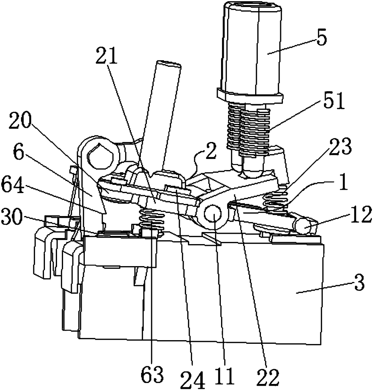
[0043] This embodiment provides a leakage protection device, such as image 3 As shown, it includes: a bracket 3, a transmission mechanism and a power mechanism, wherein the bracket 3 is provided with a static contact 30 connected to the load circuit; the transmission mechanism is provided with a moving contact 20 corresponding to the static contact 30, and the transmission The mechanism is movably connected between the first reset unit and the protection unit, and it has a locking position cooperating with the protection unit; the power mechanism includes a protection unit that drives the dynamic and static contacts to separate when leakage occurs, and drives the dynamic and static contacts The first reset unit driven by external force and the second reset unit with pre-stored force to restore conduction, wherein the second reset unit is arranged on the transmission mechanism, and the protection unit and the first reset unit are installed between the bracket 3 and the transmis...


PUM


Abstract

The invention provides an electric leakage protection device which comprises the components of a bracket on which a static contact which is connected with a load circuit is arranged; a transmission mechanism on which a moving contact that corresponds with the static contact is arranged, wherein the transmission mechanism is movably connected between a first resetting unit and a protecting unit andis provided with a locking device that is in matched locking with the protecting unit. The electric leakage protection device further comprises a power mechanism which comprises a protecting unit that drives the moving contact and the static contact for separation in electric leakage, a first resetting unit which drives the moving contact and the static contact for recovering conduction, and a second resetting unit which is arranged on the transmission mechanism, wherein the protecting unit and the first resetting unit are arranged on the bracket. Because a clearance between the moving contact and the static contact is not affected by the first resetting unit after the transmission mechanism resets to a locking position, a technical defect of easy burning of the moving contact and the static contact when a resetting button is not pressed to an appropriate position, thereby prolonging service life.

Description

technical field [0001] The invention relates to the technical field of electrical protection equipment, in particular to a leakage protection device. Background technique [0002] Leakage protectors are widely used because they can disconnect the line in time when a leakage fault occurs in the equipment, thereby ensuring the safety of equipment and personal safety. [0003] Chinese patent document CN206401254U discloses a moving first bracket for an earth leakage protector, which mainly includes a circuit board, a reset lever, a contact pressure plate, a moving contact, a static contact, a pin seat, and a tripping coil assembly, and one end of the static contact is arranged On the circuit board, the other end is in contact with the contact pressure plate, the moving contact is set on the pin seat, and the pin seat drives the moving contact to fit or separate from the static contact under the action of the reset rod, and the tripping coil assembly includes a release The buck...

Claims


Application Information

Patent Timeline
Patent Type & Authority Applications(China)
IPC IPC(8): H01H71/58
CPCH01H71/58
Inventor 郑建中罗国红罗耀文
Owner ZHEJIANG ZHONGXUN ELECTRONICS
Why Eureka
Try Eureka