A high-voltage polarized solar cell surface autonomous lunar dust removal vehicle

A solar cell, high-voltage technology, applied in electrostatic cleaning, cleaning methods using tools, electrical components, etc., can solve the problems of high energy consumption, low work efficiency, low safety of moon dust removal devices, etc., and achieves applicability. Wide range of effects with low energy consumption

Active Publication Date: 2021-06-01
HARBIN INST OF TECH
View PDF5 Cites 0 Cited by
  • Summary
  • Abstract
  • Description
  • Claims
  • Application Information

AI Technical Summary

Problems solved by technology

[0007] In order to solve the problems of low safety, small application range, low working efficiency and high energy consumption in the existing moon dust removal device, the present invention further provides a self-clearing trolley for moon dust on the surface of solar cells with high voltage polarization

Method used


Image

  • A high-voltage polarized solar cell surface autonomous lunar dust removal vehicle
  • A high-voltage polarized solar cell surface autonomous lunar dust removal vehicle
  • A high-voltage polarized solar cell surface autonomous lunar dust removal vehicle

Examples


specific Embodiment approach 1

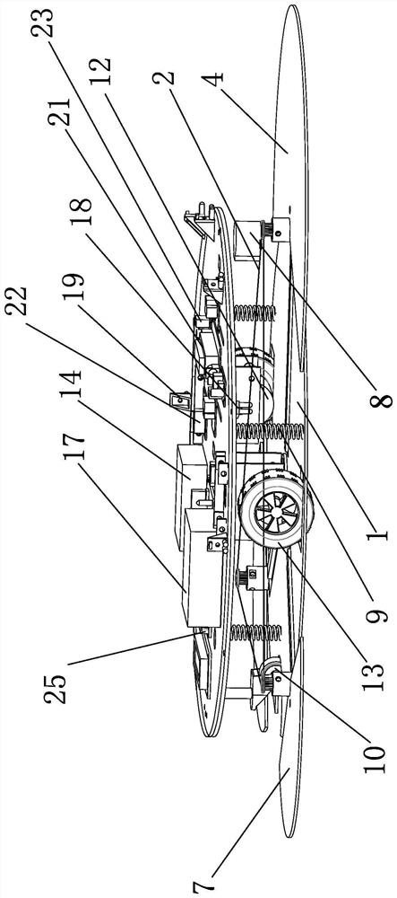
[0026] Specific implementation mode one: combine Figure 1 to Figure 5 To illustrate this embodiment, the device described in this embodiment includes a dust removal layer, a driving layer, an energy supply layer and a circular support plate;

[0027] The upper surface of the circular support plate is provided with a cylindrical cavity, the diameter of the bottom surface of the cylindrical cavity is smaller than the diameter of the upper surface of the support plate, and a plurality of cliff-avoiding infrared sensors 18 are equidistantly arranged on the lower surface of the support plate along the circumferential direction. At the edge, a plurality of obstacle avoidance infrared sensors 19 are equidistantly arranged on the edge of the upper surface of the support plate along the circumferential direction, and the center of the lower surface of the support plate is provided with a stepper motor 3;

[0028] The dust removal layer includes a circular bottom plate 1, a timing belt...

specific Embodiment approach 2

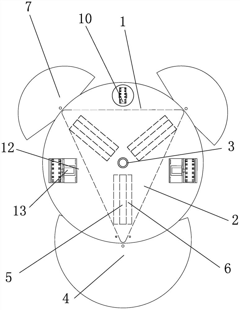
[0033] Specific implementation mode two: combination Figure 1 to Figure 4 Describe this embodiment, the shape of the dust removal main electrode 4 in this embodiment is a sector with a central angle of 180°-270°, and the other composition methods are the same as in the first embodiment.

specific Embodiment approach 3

[0034] Specific implementation mode three: combination Figure 1 to Figure 4 Describe this embodiment, the shape of the auxiliary dedusting electrode 7 in this embodiment is a sector with a central angle of 90°-180°, and other composition methods are the same as those in Embodiment 1.

[0035] The dust removal electrodes are designed in three pieces, all of which are fan-shaped to ensure the maximum dust removal electrodes. The front electrode and the rear electrode should be able to cover the width direction of the vehicle to ensure that no dust is missed.


PUM

PropertyMeasurementUnit
angleaaaaaaaaaa
angleaaaaaaaaaa
thicknessaaaaaaaaaa

Abstract

A high-voltage polarized self-clearing trolley for moon dust on the surface of solar cells belongs to the field of moon dust removal technology, mainly to solve the problems of low safety, small application range, low work efficiency and problems in moon dust removal devices in the prior art. For the problem of high energy consumption, the present invention includes a dust removal layer, a driving layer, an energy supply layer and a circular support plate, and uses a high-voltage module power supply to convert the 12V DC voltage input by the solar panel into an adjustable high-voltage power supply of 0-3000V. Connect the high-voltage output end to the protected plane and the dust removal electrode respectively. When the two are sufficiently close (2-6mm), a strong electric field will be generated between them. Under the action of the electric field, the moon dust particles will be polarized and brought along with the dust removal The opposite charge of the electrode is adsorbed to the dust removal electrode under the action of the electric field force, and the invention is mainly used for removing the moon dust on the lunar solar panel.

Description

technical field [0001] The invention relates to the technical field of moon dust removal, in particular to a self-clearing trolley for moon dust on the surface of a high-voltage polarized solar cell. Background technique [0002] Moon dust is produced by factors such as meteorite impact on the lunar surface, long-term exposure to the radiation environment of high-energy charged particles, and the nearly 300°C temperature difference between day and night that causes lunar rocks to expand with heat, contract with cold, and crack. Therefore, it is inherently fine and uniform. The diameter is about 40 ~ 120μm, easy to charge, strong adhesion and so on. It is easy to accumulate on the surface of sensitive power components such as photoelectric arrays and radiators, reducing their performance. Currently, there are three main methods for removing moon dust: [0003] Electric curtain dust removal, it is to design a layer of parallel and alternating electric curtains on the protecte...

Claims


Application Information

Patent Timeline
Patent Type & Authority Patents(China)
IPC IPC(8): B08B6/00B08B13/00B08B1/02H02S40/10
CPCB08B1/002B08B1/02B08B6/00B08B13/00H02S40/10Y02E10/50
Inventor 姜晶闫晓腾樊真权
Owner HARBIN INST OF TECH
Why Eureka
Try Eureka