Terminal block

A terminal, surface contact technology, applied in the direction of connection, conductive connection, electrical component connection, etc., can solve the problems of rotation dislocation of the upper slider and lower slider, sliding obstruction, terminal breakdown, etc., to ensure safety and reliability. Reliability, smooth lateral sliding, and the effect of avoiding rotational dislocation

Active Publication Date: 2013-06-19
CHENGDU RELIANCE ELECTRIC
View PDF4 Cites 0 Cited by
  • Summary
  • Abstract
  • Description
  • Claims
  • Application Information

AI Technical Summary

Problems solved by technology

[0004] 1. After the screw is loosened, the lower slider is out of contact with the conductive sheet, but the upper slider is always lapped on the upper surface of the conductive sheet due to the influence of its own gravity. When the upper slider needs to be moved laterally, the upper slider The end of the conductive sheet is easy to hit the cross-section of the conductive sheet, causing the sliding to be blocked
[0005] 2. When sliding the upper slider and the lower slider horizontally, if the sliding is not in place, the electrical gap between the conductive sheets will be insufficient, which will easily cause the terminal to be broken down when the overvoltage occurs
[0006] 3. When the screws are tightened with force, the upper slider and the lower slider are likely to be rotated and dislocated along the tightening direction, resulting in poor contact between the upper slider, the lower slider and the conductive sheet, posing a safety hazard
[0007] 4. When the current connection is realized, the upper slider and the lower slider only contact the upper and lower surfaces of the conductive sheet, which may easily cause the current to be unstable
[0008] 5. The metal parts of the upper slider, lower slider and conductive sheet located in the terminal base are exposed, that is, the metal parts can be touched directly by hand, which is prone to electric shock accidents, and the safety cannot be guaranteed.

Method used


Image

  • Terminal block
  • Terminal block

Examples


Embodiment Construction

[0022] In order to understand the purpose, technical solutions and beneficial effects of the present invention more clearly, the present invention will be further described below in conjunction with the accompanying drawings, but the protection scope of the present invention is not limited to the following examples.

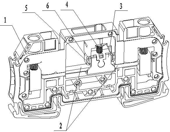
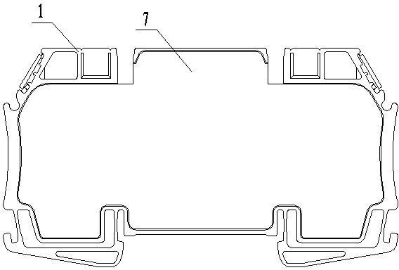
[0023] Such as figure 1 and figure 2 As shown, a connection terminal includes a base body 1, a conductive sheet 2 arranged in the base body 1, and a control device for connecting or cutting off the current between the conductive sheets 2, and the control device includes a sliding sleeve on the conductive sheet 2. The slider clamp 3 is provided with a lifting device 6 located above the conductive sheet 2 and adjusting the slider 5 through the rotating device 4; the lifting device 6 is set on the rotating device 4, the slider 5 is placed in the lifting piece, when the current needs to be connected, the slider 5 and the inner bottom of the slider clip 3 work toget...


PUM


Abstract

The invention discloses a terminal block, comprising a substrate (1), conductive chips (2) on the substrate (1) and a control device for switching on or off the currents among the conductive chips (2), wherein the control device comprises sliding clamps (3) which are sleeved on the conductive chips (2) slidably; and each sliding clamp (3) is internally provided with a lifting device (6) which is arranged above the conductive chips (2) and used for regulating sliders (5) by a rotary device (4). The terminal block can overcome the problem that sliders are always overlapped on the conductive chips in the prior art, and can be smooth in horizontal sliding movement and easy to slide to the proper position, so that electric clearances among the conductive chips can be ensured, thus the breakdown hazard does not occur although the overvoltage happens, thereby being good in safety; meanwhile, the terminal block can avoid the sliders from dislocating due to rotation along the fastening direction, thus the contact among the conductive chips is always in a good state.

Description

technical field [0001] The invention belongs to the field of electric connectors, and in particular relates to a connection terminal. Background technique [0002] In the field of electrical connectors, terminals are one of the most important parts to realize electrical connections. The structure of existing terminals mainly includes a base, a conductive sheet arranged on the base, and an upper slider and a lower slider set on the screw. , wherein the screws are arranged longitudinally between the conductive sheets, the upper slider is located at the upper end of the conductive sheet, the lower slider is located at the lower end of the conductive sheet, both the upper slider and the lower slider are rotated by the screw and laterally slide the upper slider and the lower slider The block realizes the connection and cut-off of the current between the conductive sheets, that is, when the screw is tightened, the upper and lower sliders clamp the upper and lower surfaces of the c...

Claims


Application Information

Patent Timeline
Patent Type & Authority Patents(China)
IPC IPC(8): H01R11/01H01R13/502H01R13/70
Inventor 任志昊邹建
Owner CHENGDU RELIANCE ELECTRIC
Why Eureka
Try Eureka