Synchronous assembling and conveying production line applied to engine production process

A production process and production line technology, applied in the field of synchronous assembly and conveying production lines, can solve problems such as low efficiency, high labor intensity of employees, and inability to meet production costs, and achieve the effects of reliable fixing, good protection, and simple and fast fixing methods.

Active Publication Date: 2018-08-21
ANHUI QUANCHAI TIANHE MACHINERY
View PDF7 Cites 0 Cited by
  • Summary
  • Abstract
  • Description
  • Claims
  • Application Information

AI Technical Summary

Problems solved by technology

In order to reduce production costs, different models will be assembled on the same automobile production site, but the existing synchronous assembly and conveying production line for engine installation stations can only position engines of one appearance size for assembly. During the production line, it is necessary to make engine limit slots with different widths and engine installation stations for different vehicle models to assemble and convey the production line synchronously. When the corresponding models are produced, the corresponding matching engines are installed on the automobile production line
[0004] Therefore, the synchronous assembly and conveying production line of the engine installation station in the existing structure has the following deficiencies: first, it can only correspond to one type of vehicle, and needs to be replaced when switching between different types of vehicles, resulting in inconvenient assembly, low efficiency, and high labor intensity for employees; Second, frequent disassembly and installation will cause the bolts that fix the pallet to the automobile production line to slip, which may easily cause hard damage to the engine; third, it is necessary to reserve space for the synchronous assembly and conveying production line that is not used online, and it will cost a certain amount of manpower and material resources To maintain, can not meet the requirements of production costs;

Method used


Image

  • Synchronous assembling and conveying production line applied to engine production process
  • Synchronous assembling and conveying production line applied to engine production process
  • Synchronous assembling and conveying production line applied to engine production process

Examples


Embodiment Construction

[0022] The following will clearly and completely describe the technical solutions in the embodiments of the present invention with reference to the accompanying drawings in the embodiments of the present invention. Obviously, the described embodiments are only some, not all, embodiments of the present invention. Based on the embodiments of the present invention, all other embodiments obtained by persons of ordinary skill in the art without making creative efforts belong to the protection scope of the present invention.

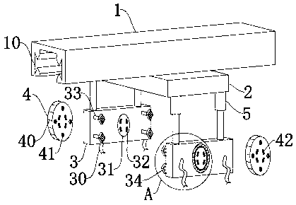
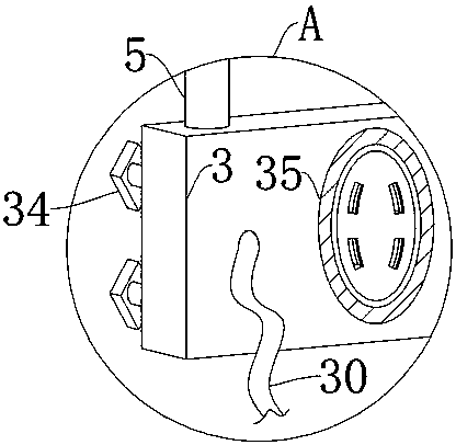
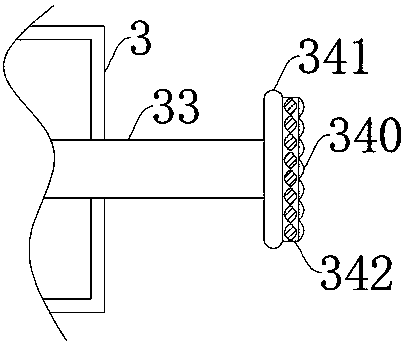
[0023] Such as Figure 1-3 Shown: a synchronous assembly and conveying production line used in the engine production process, including a production equipment rack 1 and an assembly bearing block 2, the assembly bearing block 2 is arranged at the lower end of the production equipment rack 1, and the production equipment rack 1 faces One end of the assembling bearing block 2 is provided with a conveying track 10, and the assembling bearing block 2 is correspond...


PUM


Abstract

The invention provides a synchronous assembling and conveying production line applied to an engine production process. Two hydraulic rods are arranged on each limiting-fixing plate, and four rodless air cylinders are arranged and fixed on each limiting-fixing plate, so that engines can be firmly fixed on the synchronous assembling and conveying production line, and the synchronous assembling and conveying production line can be applied to the engines of different heights; open slots are arranged on the outer sides of linkage rotating discs, screw threads are arranged on the inner walls of theopen slots, the diameters of control rotating discs are greater than those of the linkage rotating discs, and second threaded slots are arranged on the inner sides of threaded connecting holes, so that during the work of the synchronous assembling and conveying production line, the positions of the engines can be rotated at any time through the cooperation between the control rotating discs and the linkage rotating discs; and the second threaded slots and the first threaded slots are always positioned in one and the same transverse horizontal plane, the threaded connecting holes and the open slots are always positioned in one and the same transverse horizontal plane, non-slip friction blocks are arranged on the outer sides of elastic blocks, and bearing plates are arranged on the inner sides of the elastic blocks, so that during the use of the synchronous assembling and conveying production line, the engines can be fixed in a simple and quick manner as well as better protected.

Description

technical field [0001] The invention relates to the technical field related to the engine production process, in particular to a synchronous assembly and conveying production line used in the engine production process. Background technique [0002] At present, various automobile engine enterprises, in the assembly process of automobile engines, first sub-assemble the cylinder block assembly, crank-connecting rod system, cylinder head assembly and valve train, and then put the sub-assembled cylinder block on the engine assembly line. On the engine assembly line, it is necessary to support the engine block before assembling the divided cylinder head and other peripheral accessories of the engine, while the engine assembly line mostly supports the engine body part in the form of a tray, and the engine tray is placed on the engine assembly line Circulation, so that the engine can assemble parts one by one in sequence until the engine assembly is completed and off the assembly li...

Claims


Application Information

Patent Timeline
Patent Type & Authority Applications(China)
IPC IPC(8): B23P19/00
CPCB23P19/008
Inventor 安东
Owner ANHUI QUANCHAI TIANHE MACHINERY
Why Eureka
Try Eureka