
Clamping tool convenient for double-sided machining

A technology of clamping tooling and double-sided processing, which is applied in metal processing, metal processing equipment, metal processing machinery parts, etc., can solve the problems of reduced parallelism of processing surfaces, reduced production efficiency, and easy changes in positioning references, etc., to achieve improved The effect of work efficiency, convenient operation and simple structure

Inactive Publication Date: 2018-08-21
柳州市钜诚科技有限公司
View PDF2 Cites 23 Cited by
  • Summary
  • Abstract
  • Description
  • Claims
  • Application Information

AI Technical Summary

Problems solved by technology

[0002] In the process of mechanical processing, when two opposite processing surfaces of the workpiece need to be processed, the two opposite processing surfaces can be processed separately, that is, when one side is processed, the other side is processed, but in this way, the workpiece needs to be processed Turn over and perform two processing, that is, loosen the workpiece and carry out the second clamping, which reduces the production efficiency. At the same time, the positioning reference of the workpiece is easy to change during the process of picking and placing the workpiece, resulting in a decrease in the parallelism of the two processing surfaces, which cannot meet the customer's requirements. need

Method used

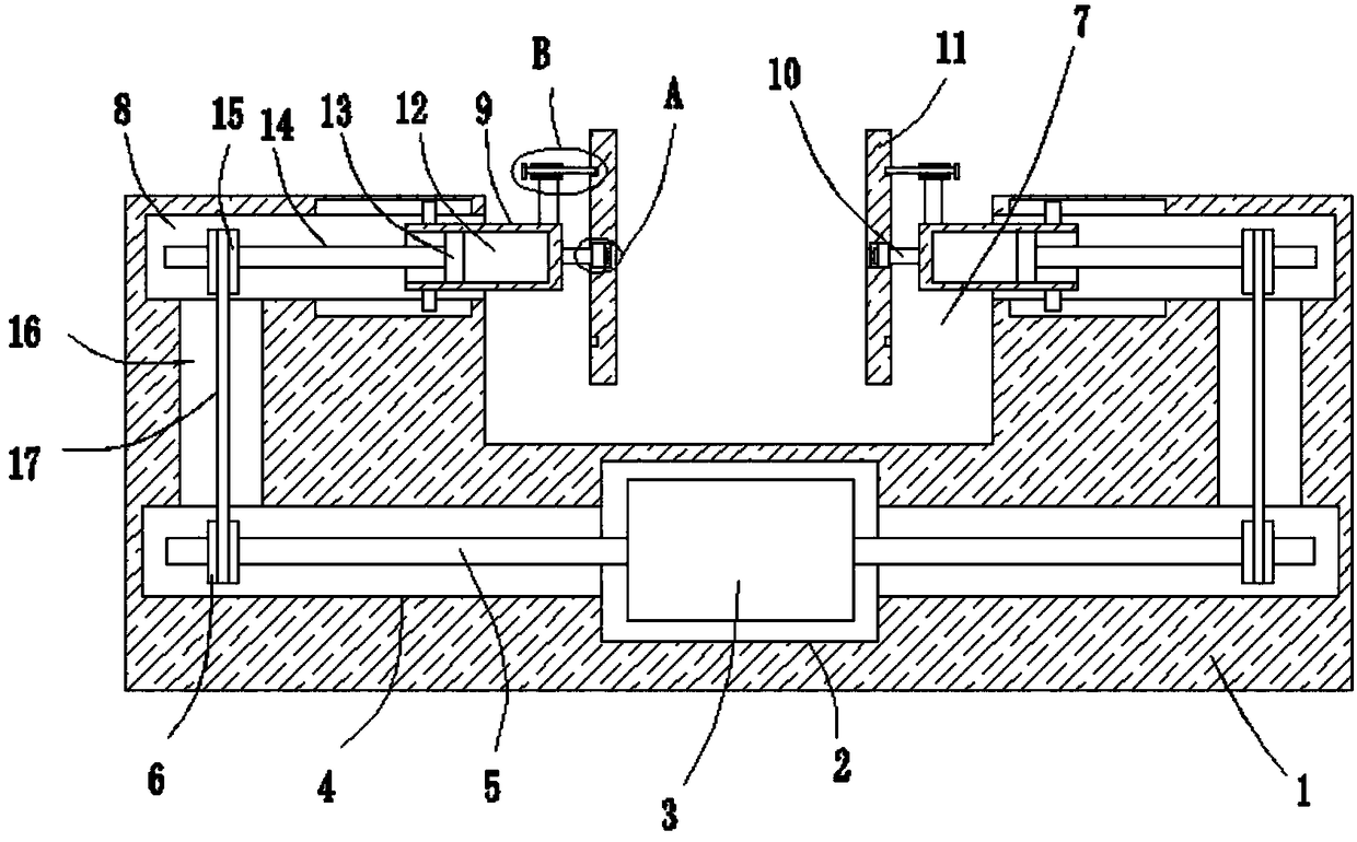

Image

  • Clamping tool convenient for double-sided machining
  • Clamping tool convenient for double-sided machining
  • Clamping tool convenient for double-sided machining

Examples


Embodiment

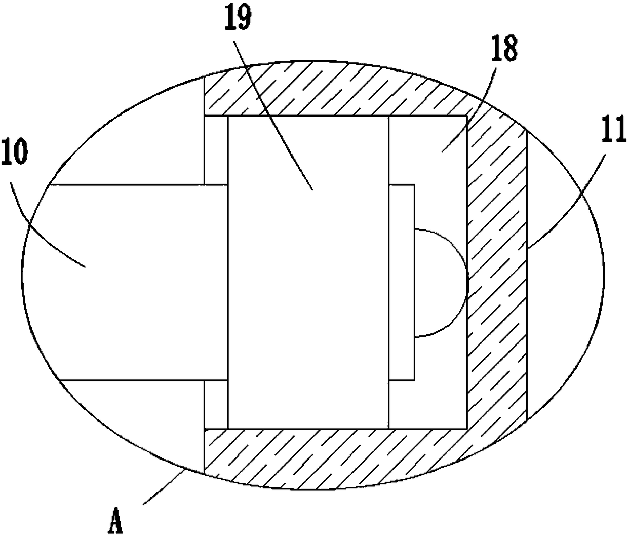
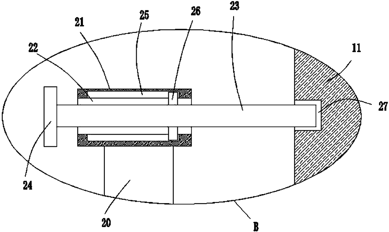
[0022] refer to Figure 1-5 In this embodiment, a clamping tool for double-sided processing is proposed, including a base 1, a motor cavity 2 is opened on the base 1, a motor 3 is fixedly installed in the motor cavity 2, and the inner walls of both sides of the motor cavity 2 are A rotating slot 4 is opened, and a rotating shaft 5 is installed in the rotating slot 4. The end of the rotating shaft 5 close to the motor chamber 2 extends into the motor chamber 2 and is fixedly connected with the output shaft of the motor 3. The first gear is fixedly sleeved on the rotating shaft 5 6. The top side of the base 1 is provided with a through groove 7, and the inner walls of both sides of the through groove 7 are provided with a chute 8, and a slide rod 9 is slidably installed in the chute 8, and the end of the slide rod 9 close to the through groove 7 extends to A connecting rod 10 is fixedly installed in the through groove 7, and a chuck 11 is installed on the side where the two conn...


PUM


Abstract

The invention discloses a clamping tool convenient for double-sided machining. The clamping tool comprises a base, wherein a motor cavity is formed in the base; a motor is fixedly mounted inside the motor cavity; rotating slots are formed in the inner walls of the two sides of the motor cavity; rotating shafts are rotationally mounted inside the rotating slots; one ends, close to the motor cavity,of the rotating shaft stretch into the motor cavity and are fixedly connected with an output shaft of the motor; the rotating shafts are fixedly sleeved by first gears; a through slot is formed in the top side of the base; sliding slots are formed in the inner walls of the two sides of the through slot; sliding rods are mounted inside the sliding slots in a sliding manner; one ends, close to thethrough slot, of the sliding rods stretch into the through slot, and connecting rods are fixedly mounted at the ends; clamping heads are rotationally mounted on one sides, close to each other, of thetwo connecting rods; threaded slots are formed in one ends, away from the through slot, of the sliding rods. The clamping tool can clamp a workpiece firmly; when the other side is required to be machined, the workpiece can be directly flipped and a secondary clamping operation is not required, so that the working efficiency is greatly improved; the clamping tool is simple in structure and convenient to operate.

Description

technical field [0001] The invention relates to the technical field of clamps, in particular to a clamping tool for double-sided processing. Background technique [0002] In the process of mechanical processing, when two opposite processing surfaces of the workpiece need to be processed, the two opposite processing surfaces can be processed separately, that is, when one side is processed, the other side is processed, but in this way, the workpiece needs to be processed Turn over and perform two processing, that is, loosen the workpiece and carry out the second clamping, which reduces the production efficiency. At the same time, the positioning reference of the workpiece is easy to change during the process of picking and placing the workpiece, resulting in a decrease in the parallelism of the two processing surfaces, which cannot meet the customer's requirements. need. Contents of the invention [0003] Based on the technical problems existing in the background technology...

Claims


Application Information

Patent Timeline
Patent Type & Authority Applications(China)
IPC IPC(8): B23Q3/06B23Q7/00
CPCB23Q3/06B23Q7/00
Inventor 杜家好韦光开唐启成
Owner 柳州市钜诚科技有限公司
Learn More