
Charging pile for new energy vehicles

A technology of new energy vehicles and charging piles, applied in electric vehicle charging technology, charging stations, electric vehicles, etc., can solve problems such as contact arcs, operational errors, dangers, etc., and achieve improved service life, convenient use, and ingenious transmission structure Effect

Inactive Publication Date: 2020-12-08
CHONGQING VOCATIONAL COLLEGE OF TRANSPORTATION
View PDF7 Cites 0 Cited by
  • Summary
  • Abstract
  • Description
  • Claims
  • Application Information

AI Technical Summary

Problems solved by technology

However, the existing charging piles need to manually put the charging cable back into the charging pile after the charging is completed, but the charging cables are generally heavy, which brings great inconvenience to the user.
The charging line of the traditional charging pile is exposed outside the charging pile for a long time, and there is a risk of the charging line being crushed and damaged by the electric vehicle; in addition, due to the high charging voltage of the charging pile of the electric vehicle, if the power supply is not disconnected, it will directly If the charging gun is plugged into the charging port of the car, it is very likely that a contact arc will be generated, which will cause danger. The current charging pile with power-off function is more complicated to operate. The charging head does not have an automatic power-off function and requires manual operation. , prone to operational errors, it is difficult to ensure the safety of charging

Method used


Image

  • Charging pile for new energy vehicles
  • Charging pile for new energy vehicles
  • Charging pile for new energy vehicles

Examples


Embodiment Construction

[0011] In order to make the purpose, technical solutions and advantages of the embodiments of the present invention clearer, the technical solutions in the embodiments of the present invention will be clearly and completely described below in conjunction with the drawings in the embodiments of the present invention. Obviously, the described embodiments It is a part of embodiments of the present invention, but not all embodiments. Based on the embodiments of the present invention, all other embodiments obtained by persons of ordinary skill in the art without creative efforts fall within the protection scope of the present invention.

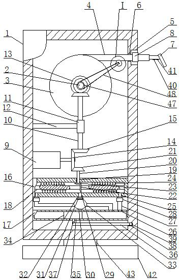
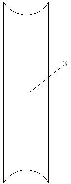
[0012]A charging pile for new energy vehicles, as shown in the figure, includes a housing 1, the upper part of the housing 1 is provided with a first horizontal shaft 2, and the front and rear ends of the first horizontal shaft 2 are respectively movably connected with bearings on the inner wall of the housing 1 , the storage turntable 3 is fixedl...


PUM


Abstract

The utility model relates to a charging pile for new energy automobiles. The charging pile includes a casing; a first horizontal shaft is arranged on an upper part of the casing; the front and the rear ends of the first horizontal shafts are movably connected with inner wall bearings of the casing; a storage turntable is fixedly mounted on the first horizontal shaft; a cable is arranged on the storage turntable; a groove is formed in a part near the upper end, of the right side surface of the casing; the groove communicates with the interior of the casing through a first through hole; a free end of the cable passes through the first through hole and is located outside the casing; the free end of the cable is fixedly mounted with a charging head; a limiting block is fixedly arranged on a part near the free end of the cable; the limiting block can cooperate with the groove; a lateral motor is fixedly mounted on the left side wall of the housing; an upper side of an end of an output shaftof the motor has a first vertical shaft; the first vertical shaft is sleeved with a shaft sleeve through a bearing; and the shaft sleeve is fixedly connected with the inner wall of the casing througha bracket. The invention can store the cable by electric power when the battery is not charged, the situation that the cable is exposed outside at all times and is worn can be prevented, and the service life of the cable is prolonged.

Description

technical field [0001] The invention belongs to the technical field of new energy electric vehicles, in particular to a charging pile for new energy vehicles. Background technique [0002] With the rapid growth of our country's economy, the pollution of the natural environment on which human beings rely is becoming increasingly serious. In order to solve the problem of environmental pollution, electric vehicles have become an important measure to replace traditional fuel vehicles. The electric vehicle itself does not emit carbon dioxide and has no tail gas pollution, which is very beneficial to the control of environmental pollution and the reduction of tail gas emissions. However, in the existing charging piles, after the charging is completed, the charging cables need to be artificially put back into the charging piles, but the charging cables are generally heavy, which brings great inconvenience to users. The charging line of the traditional charging pile is exposed outs...

Claims


Application Information

Patent Timeline
Patent Type & Authority Patents(China)
IPC IPC(8): B60L53/18B65H75/38B65H75/44
CPCB65H75/38B65H75/44B65H2701/34B60L53/16B60L53/18B60L53/31Y02T10/70Y02T10/7072Y02T90/12Y02T90/14
Inventor 周桂源黄欣严伟民
Owner CHONGQING VOCATIONAL COLLEGE OF TRANSPORTATION
Learn More