Hypersonic flight vehicle leading edge heat protection method based on gradient porous material

A hypersonic, gradient porous technology, applied to aircraft parts, fuselage, transportation and packaging, etc., can solve the problems of the worst cooling effect and high temperature, and achieve the effect of high-precision positioning and quantitative injection

Active Publication Date: 2018-08-21
UNIV OF SCI & TECH OF CHINA
View PDF6 Cites 17 Cited by
  • Summary
  • Abstract
  • Description
  • Claims
  • Application Information

AI Technical Summary

Problems solved by technology

[0004] However, if figure 2 As shown, the aerodynamic force and aerodynamic heat are the strongest in the stagnation point region of the leading edge of the hypersonic vehicle, and the cooling effect in this region is often the worst, and the temperature before and after cooling is always the highest

Method used


Image

  • Hypersonic flight vehicle leading edge heat protection method based on gradient porous material
  • Hypersonic flight vehicle leading edge heat protection method based on gradient porous material
  • Hypersonic flight vehicle leading edge heat protection method based on gradient porous material

Examples


specific Embodiment approach

[0015] The preferred embodiment of the thermal protection method for the leading edge of a hypersonic vehicle based on gradient porous materials of the present invention is:

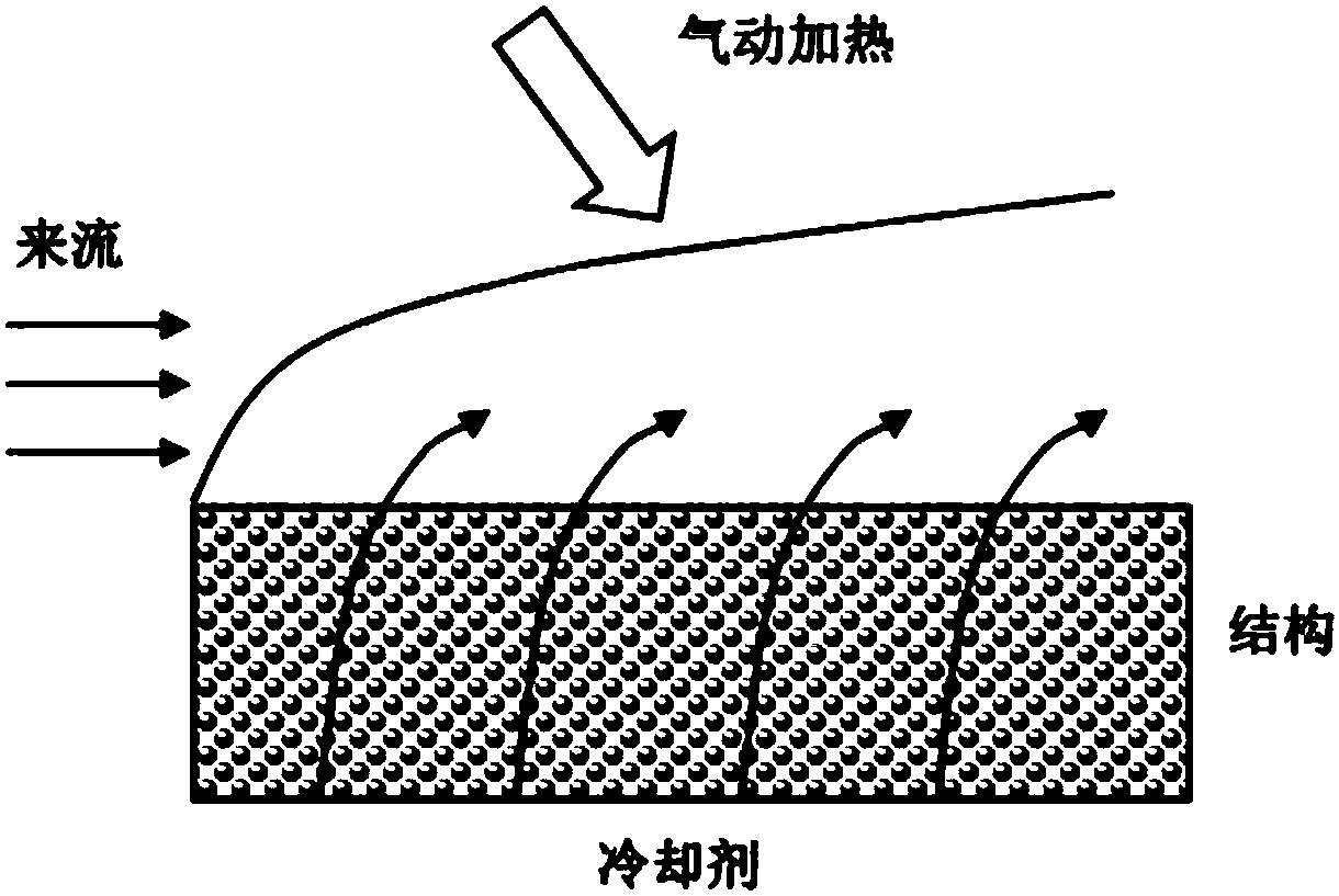
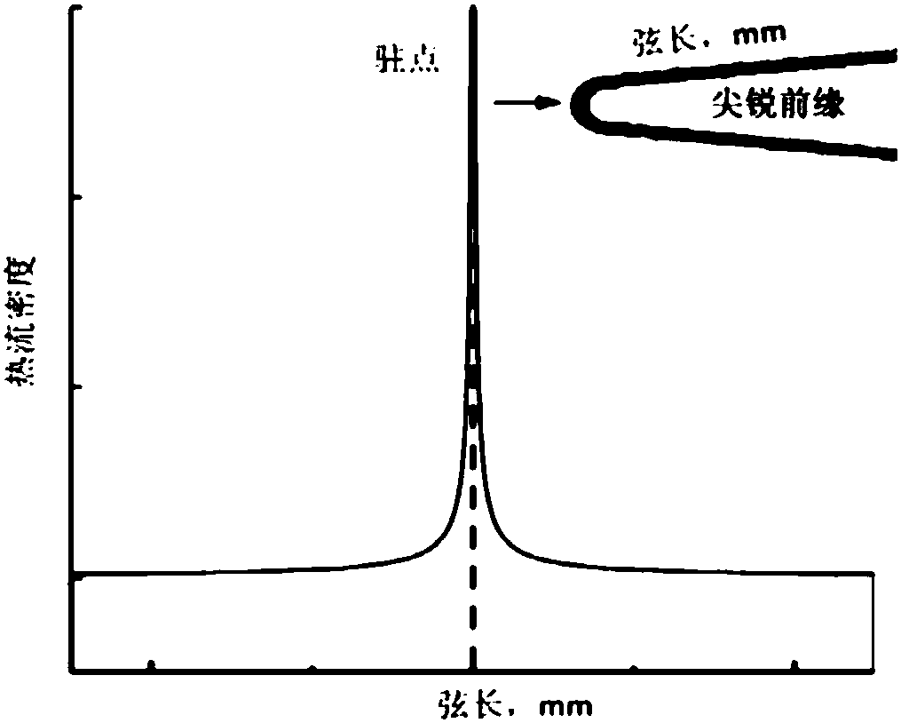
[0016] A porous front with gradient porosity is prepared by using a high temperature resistant material, the porosity of the stagnation point region (front end) of the porous front is the largest, and the porosity decreases backward;

[0017] A cooling pipe is fixedly connected to the rear of the porous leading edge, through which the coolant is injected into the cooling cavity and sprayed out on the surface of the leading edge;

[0018] When the coolant flows through the porous front, the convective heat exchange is forced to reduce the temperature of the porous front. At the same time, the coolant is injected into the high-temperature main flow through the micropores of the porous front, forming a layer of higher temperature in the stagnation point area of ​​the porous front. A thick air film blanket s...

specific Embodiment

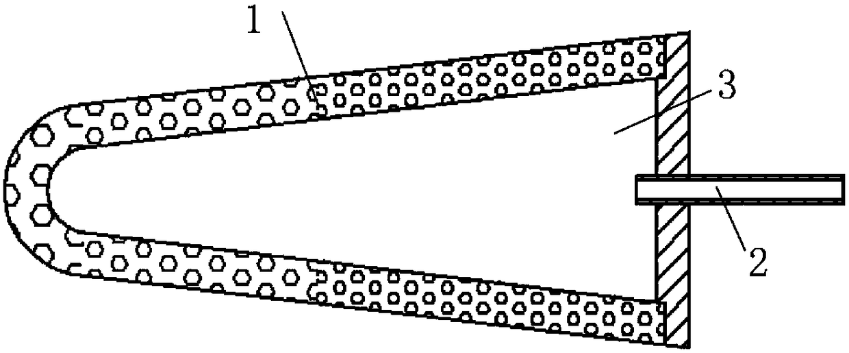
[0028] like image 3 As shown, the method of the present invention utilizes the concept of sweat cooling according to the permeability characteristics of the porous medium to complete the thermal protection of the outer surface of the front edge of the hypersonic vehicle. The method of the present invention comprises a porous front 1 made of high temperature resistant material, a cooling pipeline 2 is fixedly connected to the rear of the porous front, and the coolant is injected into the cooling chamber 3 through the cooling pipeline 2 . The coolant infiltrates into the high-temperature main flow from the micropores under the action of the pressure in the chamber.

[0029] like image 3 As shown, the material of the porous medium used in the porous front 1 and the shape of the front 1 in the method of the present invention are basically the same as those in the prior art, except that the present invention improves the properties of the porous medium used in the front 1 . The...


PUM


Abstract

The invention discloses a hypersonic flight vehicle leading edge heat protection method based on a gradient porous material. A porous leading edge with gradient porosity is prepared from a high-temperature-resistant material, the porosity of a stationary point area of the porous leading edge is the maximum, and the porosity decreases backwards; a cooling pipeline is fixedly connected with the backpart of the porous leading edge, a coolant is injected into a cooling cavity through the cooling pipeline and sprayed out of the surface of the leading edge; the coolant is forced to perform heat convection when flowing through the porous leading edge, the temperature of the porous leading edge is decreased, meanwhile, the coolant is injected in a high-temperature mainstream through micropores inthe porous leading edge, and a thicker air film covering layer is formed in the stationary point area of the porous leading edge to isolate the porous leading edge from hot flows. A traditional sweatcooling mode is optimized by use of the gradient porous material, high-accuracy positioning and quantitative injection of the coolant are realized, and the ideal heat protection effect is realized.

Description

technical field [0001] The invention relates to an active thermal protection method for a high-temperature structure surface, in particular to a thermal protection method for a leading edge of a hypersonic vehicle based on a gradient porous material. Background technique [0002] Aerospace technology is a measure of a country's scientific and technological level and comprehensive national strength, and it has a huge boost to the country's scientific and technological, military, civilian and commercial fields. As the development direction of future flight technology, hypersonic vehicles have become a key strategic project for the development of major aerospace countries. With the development of hypersonic vehicle technology, the problem of thermal protection has become increasingly prominent, especially in some key parts of hypersonic vehicle such as leading edge nose cone, wing leading edge, inlet overflow port, etc. Designing and developing efficient active thermal protect...

Claims


Application Information

Patent Timeline
Patent Type & Authority Applications(China)
IPC IPC(8): B64C1/38
CPCB64C1/38
Inventor 王建华伍楠贺菲丁锐
Owner UNIV OF SCI & TECH OF CHINA
Why Eureka
Try Eureka