Eureka AIR delivers breakthrough ideas for toughest innovation challenges, trusted by R&D personnel around the world.

Long-span steel beam installation slipping and lifting combination device and construction method thereof

A technology combining device and sliding device, applied in construction, building structure, processing of building materials, etc., can solve the problems of long occupancy time, long assembly time, and high technical requirements of cranes, so as to reduce the use of cranes, Reduce assembly time and ensure safety

Pending Publication Date: 2018-08-21
CHINA CONSTR SECOND ENG BUREAU LTD +1
View PDF5 Cites 3 Cited by
  • Summary
  • Abstract
  • Description
  • Claims
  • Application Information

AI Technical Summary

Problems solved by technology

[0004] The purpose of the present invention is to provide a large-span steel girder installation sliding and lifting combination device to solve the long occupancy time of the single hoisting and assembling steel girder to the crane in the prior art, and the operating technical requirements of the construction personnel for the aerial assembling steel girder Higher, technical issues with longer assembly times

Method used


Image

  • Long-span steel beam installation slipping and lifting combination device and construction method thereof
  • Long-span steel beam installation slipping and lifting combination device and construction method thereof
  • Long-span steel beam installation slipping and lifting combination device and construction method thereof

Examples


Embodiment Construction

[0031] In order to make the technical means, innovative features, goals and effects achieved by the present invention easy to understand, the present invention will be further described below.

[0032] The examples described here are specific specific implementations of the present invention, and are used to illustrate the concept of the present invention. They are all explanatory and exemplary, and should not be construed as limiting the implementation of the present invention and the scope of the present invention. In addition to the embodiments described here, those skilled in the art can also adopt other obvious technical solutions based on the claims of the application and the contents disclosed in the description, and these technical solutions include adopting any obvious changes made to the embodiments described here. Replacement and modified technical solutions.

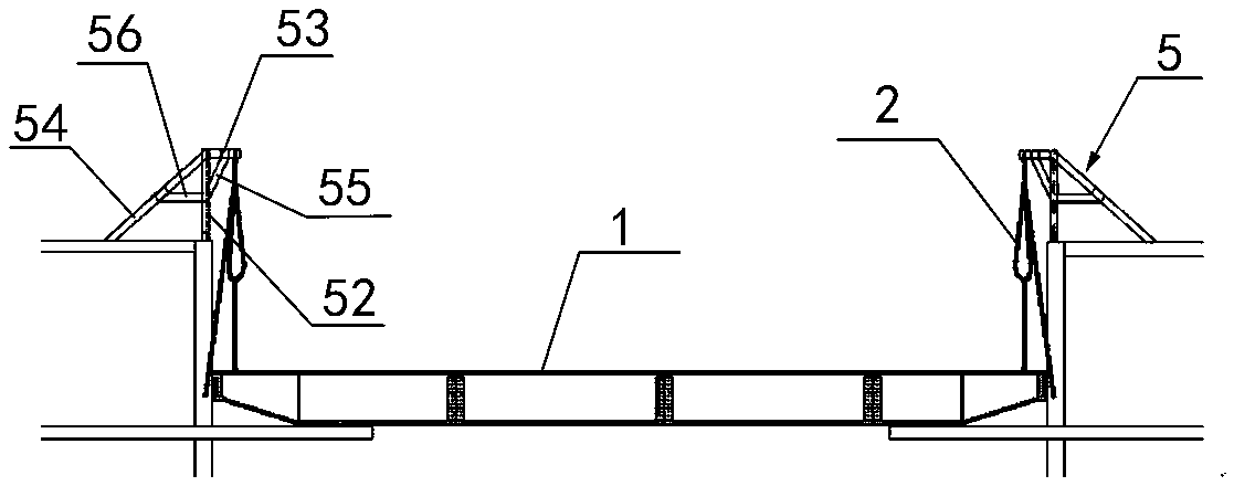
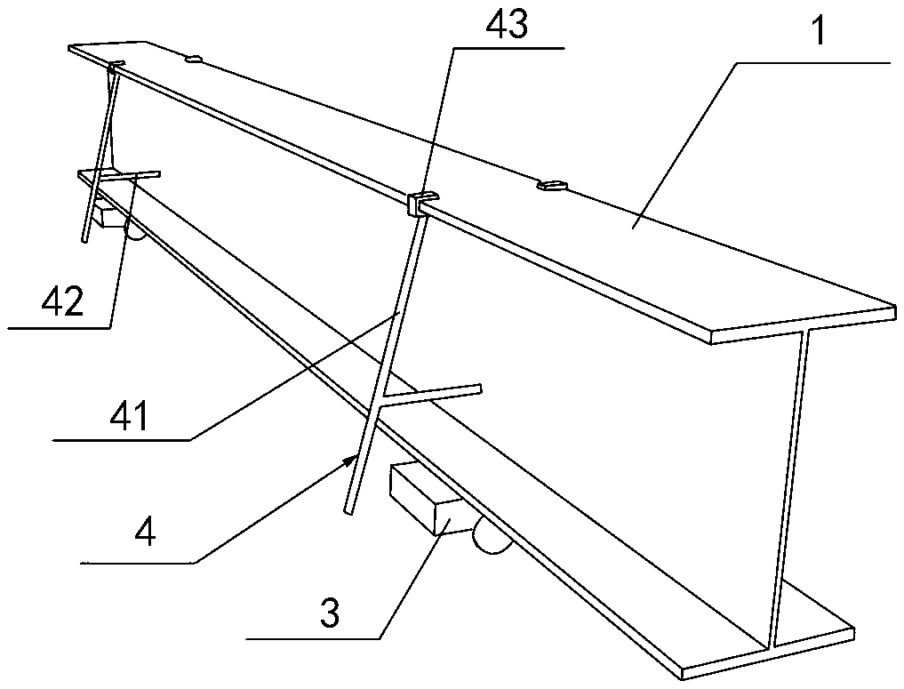
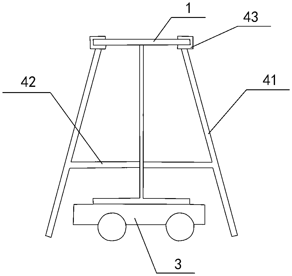
[0033] Such as Figure 1~4 As shown, a large-span steel beam installation sliding and lifting combination...


PUM

PropertyMeasurementUnit
Heightaaaaaaaaaa

Abstract

The invention relates to a long-span steel beam installation slipping and lifting combination device. The device comprises a slipping device and a lifting device; the slipping device comprises a transfer trolley arranged at the bottom of a steel beam and temporary support rods clamped at two sides of the steel beam; the lifting device is arranged on an upper floorslab above the steel beam and comprises lifting brackets symmetrically arranged on the upper floorslab and chain hoists hung on the lifting brackets. The device can achieve that long-span steel beams are used for assembling steel beams on a floorslab, and the device can easily slip on the floorslab and be lifted between the upper floorslab and a lower floorslab, assembling time is significantly shortened, the use of a crane is reduced, it can be avoided that when a tower crane is used for lifting, crossing between the lifting operation and other operations occurs, construction safety is ensured, and the construction efficiencyis improved.

Description

technical field [0001] The invention relates to the field of large-scale structure hoisting, in particular to a hoisting device for large-span steel beams and a construction method thereof. Background technique [0002] In the construction of large-scale buildings such as commercial buildings and office buildings, the hoisting of long-span beams often becomes a difficult point in construction. During the construction of the steel beam, the indoor mechanical and electrical installation, the removal of the outer frame, and the installation of the profiled steel plate are carried out at the same time, and there are many cross operations and the construction environment is complicated. In addition, there is a large hollow area in the lower floor of the long-span steel beam. After the steel beam is hoisted to the lower floor, how to assemble and hoist becomes a difficult problem. [0003] Current steel girder lifting usually includes two stages: transportation and lifting. Due ...

Claims


Application Information

Patent Timeline
IPC IPC(8): E04G21/16
CPCE04G21/162
Inventor 常海东苏铠李敏刚王加林陈天成徐晨曦王道爽张志强李国强
Owner CHINA CONSTR SECOND ENG BUREAU LTD
Why Eureka
Eureka Blog
Learn More