New-energy motor vertical head turning machine

A new energy, vertical technology, applied in the manufacture of motor generators, electrical components, electromechanical devices, etc., can solve problems such as low efficiency and easily damaged coils

Pending Publication Date: 2018-08-21
CHANGZHOU MINGNAYANG AUTOMATION EQUIP
View PDF0 Cites 2 Cited by
  • Summary
  • Abstract
  • Description
  • Claims
  • Application Information

AI Technical Summary

Problems solved by technology

This method is inefficient an

Method used


Image

  • New-energy motor vertical head turning machine
  • New-energy motor vertical head turning machine
  • New-energy motor vertical head turning machine

Examples


Embodiment Construction

[0029] The specific implementation manners of the present invention will be further described in detail below in conjunction with the accompanying drawings and embodiments. The following examples are used to illustrate the present invention, but are not intended to limit the scope of the present invention.

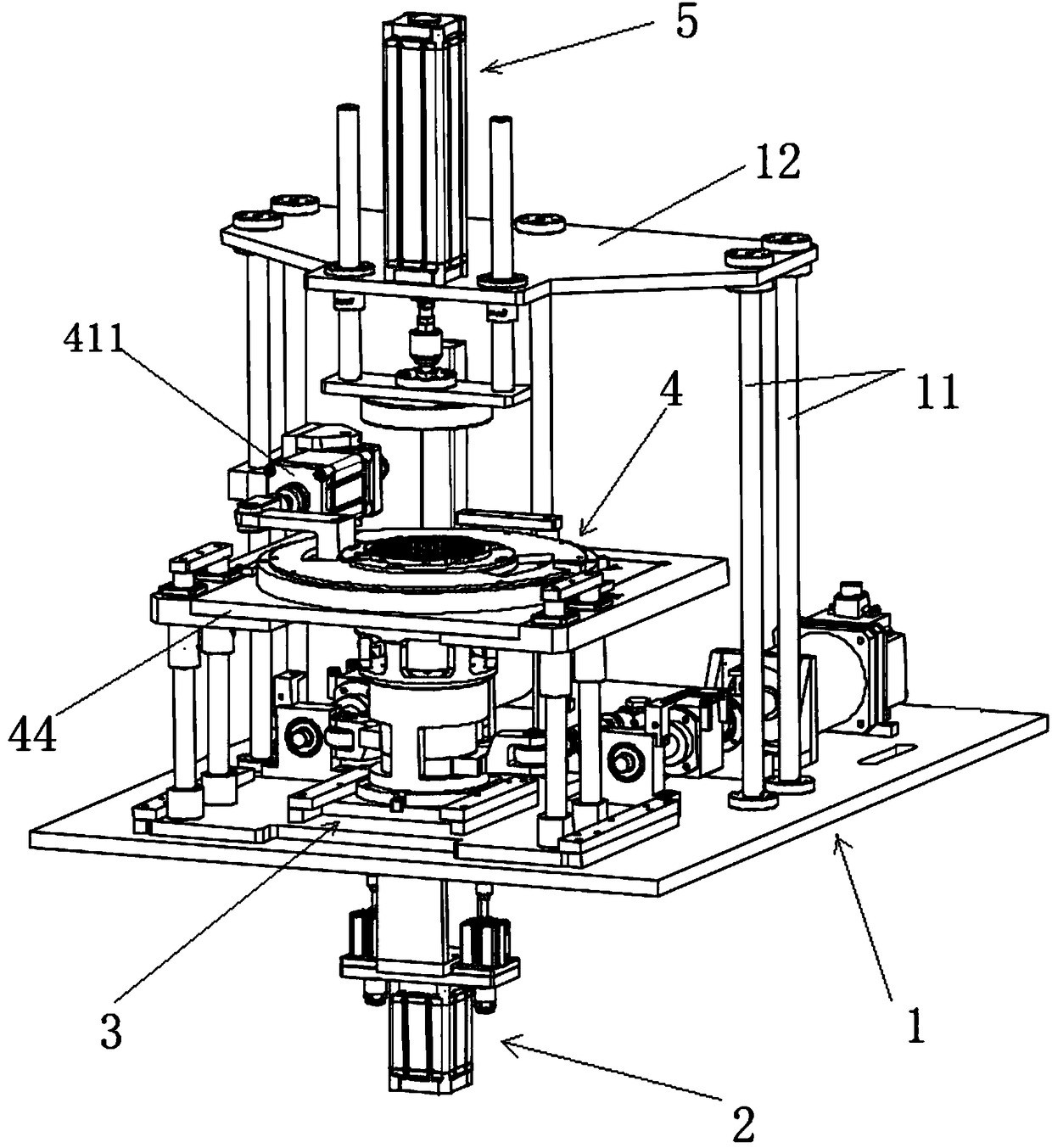
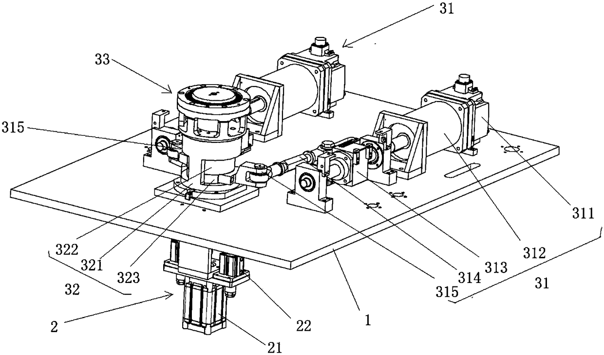
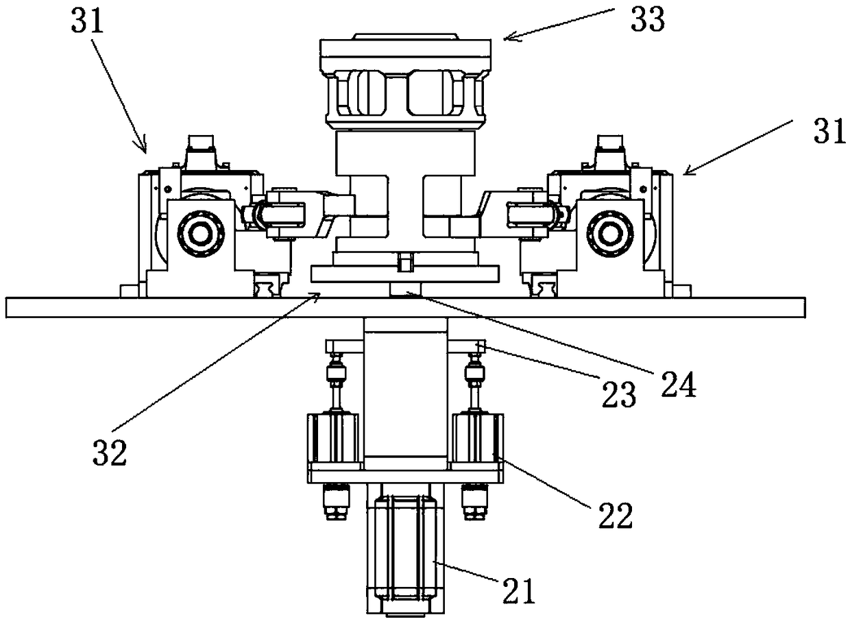
[0030] see Figure 1 to Figure 11 , The new energy motor vertical head twisting machine described in a preferred embodiment of the present invention includes a workbench 1, a blade insertion mechanism 4 is arranged on the workbench 1, and a head twist mechanism 3 is arranged at the inner bottom of the blade insertion mechanism 4 , the workbench 1 is also connected to the pressing device 5 located directly above the blade insertion mechanism 4 through a plurality of pillars 11;

[0031]Wherein the inserting mechanism 4 comprises a bottom plate 41 fixed on the workbench 1, a plurality of first pillars 42 arranged on the bottom plate 41, a supporting plate 43 is arranged on ...


PUM


Abstract

The invention relates to a new-energy motor vertical head turning machine. The machine comprises a worktable (1), the worktable (1) is provided with an sheet inserting mechanism (4), the bottom in thesheet inserting mechanism (4) is provided with a head turning mechanism (3), and the worktable (1) is further connected with a downward pressing device (5) located over the sheet inserting mechanism(4) through a plurality of support columns (11). The machine can achieve automatic head turning of a stator coil.

Description

technical field [0001] The invention relates to the field of new energy motor manufacturing, in particular to a vertical head turning machine for new energy motors. Background technique [0002] During the installation process of the new energy electronic stator, the coil in the stator coil slot needs to be bent. The existing bending device is fixed on the bottom of the stator through a mold, and the mold is manually fixed and then turned to realize coil bending. bend. This method is inefficient and prone to damage to the coil. [0003] In view of the above-mentioned defects, the designers are actively researching and innovating in order to create a new structure of new energy motor vertical head twisting machine, so that it has more industrial value. Contents of the invention [0004] In order to solve the above technical problems, the object of the present invention is to provide a new energy motor vertical head twisting machine. [0005] Technical scheme of the prese...

Claims


Application Information

Patent Timeline
IPC IPC(8): H02K15/00
CPCH02K15/005
Inventor 姚伟
Owner CHANGZHOU MINGNAYANG AUTOMATION EQUIP
Why Eureka
Try Eureka