Supercharge Your Innovation With Domain-Expert AI Agents!

Vibrating diaphragm molding jig and molding method

A jig and forming plate technology, applied in electrical components, sensors, etc., can solve the problems of difficulty in ensuring the quality of the diaphragm, inability to accurately ensure the consistency of the diaphragm, and achieve the effects of accurate positioning, high quality and simple overall structure

Pending Publication Date: 2018-08-21
苏州倍声声学技术有限公司
View PDF0 Cites 0 Cited by
  • Summary
  • Abstract
  • Description
  • Claims
  • Application Information

AI Technical Summary

Problems solved by technology

[0005] Based on this, it is necessary to provide a vibrating film forming method for the jig in the process of preparing the vibrating film, which cannot accurately ensure the consistency of the three parts of the vibrating plate, film and forming frame, so it is difficult to ensure the quality of the vibrating film after forming. Jig and molding method

Method used


Image

  • Vibrating diaphragm molding jig and molding method
  • Vibrating diaphragm molding jig and molding method
  • Vibrating diaphragm molding jig and molding method

Examples


Embodiment Construction

[0049] In order to make the above objects, features and advantages of the present invention more comprehensible, specific implementations of the present invention will be described in detail below in conjunction with the accompanying drawings. In the following description, numerous specific details are set forth in order to provide a thorough understanding of the present invention. However, the present invention can be implemented in many other ways different from those described here, and those skilled in the art can make similar improvements without departing from the connotation of the present invention, so the present invention is not limited by the specific embodiments disclosed below.

[0050] It should be noted that when an element is referred to as being “fixed” to another element, it can be directly on the other element or there can also be an intervening element. When an element is referred to as being "connected to" another element, it can be directly connected to t...


PUM


Abstract

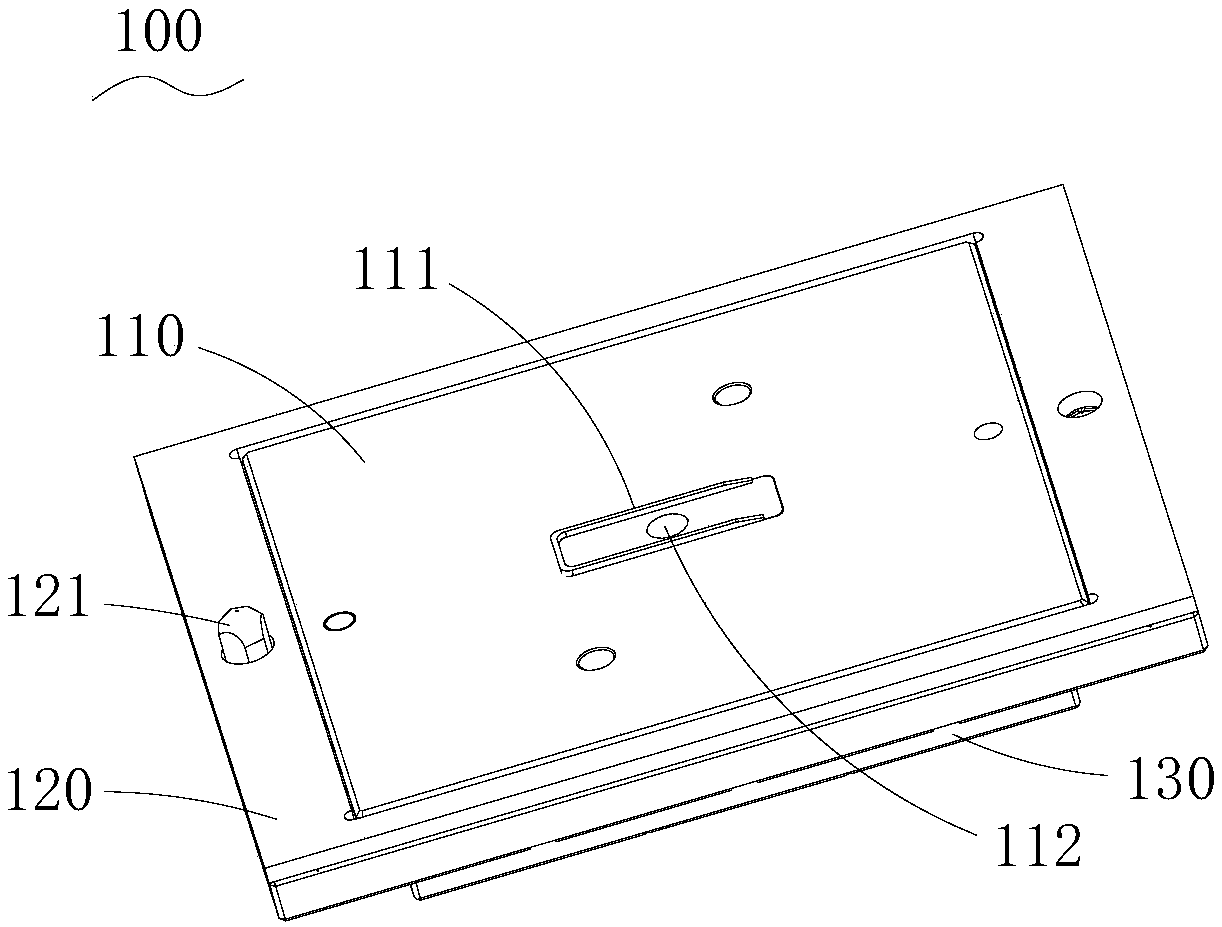
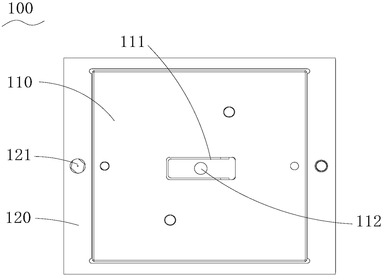
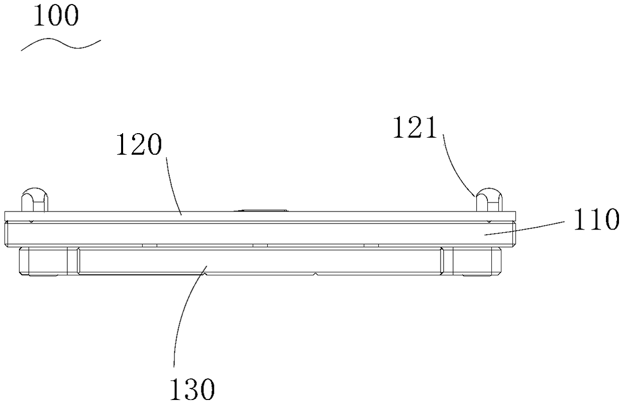
The invention discloses a vibrating diaphragm molding jig for preparing a vibrating diaphragm in a moving-iron telephone receiver. The vibrating diaphragm molding jig comprises a molding plate, at least one groove arranged on the molding plate, wherein the groove is outward bulged from the surface of the molding plate and used for positioning the vibrating diaphragm, and a through hole for suctionvacuum is formed in each groove. On the vibrating diaphragm molding jig, the groove is formed on the molding plate for vibrating diaphragm positioning, and the through hole is formed on the molding plate for sucking the vacuum, the vibrating diaphragm can be tightly adsorbed on the molding plate, and the operation is convenient; this design is simpler on the whole structure and the positioning ismore accurate, simple and practicable in the preparation of the vibrating diaphragm, and the obtained vibrating diaphragm is high in quality; multiple grooves can be formed on the molding plate so asto perform batch production. The invention further provides a vibrating diaphragm molding method using the above vibrating diaphragm molding jig. The vibrating diaphragm molding method disclosed by the invention is simpler on the structure of the molding jig, is more simplified on the steps, is especially accurate on the vibrating diaphragm positioning aspect, and is suitable for the vibrating diaphragm molded in one body.

Description

technical field [0001] The invention relates to the technical field of moving iron receivers, in particular to a diaphragm forming jig and a forming method. Background technique [0002] Moving iron receivers are mainly used in hearing aids, wearable earphones and other equipment to convert voice electrical signals into sound waves. Generally, the electro-acoustic conversion function is realized by using the principle of electromagnetic action, and the diaphragm is an important component to realize the electro-acoustic conversion function. [0003] The traditional diaphragm is generally composed of three parts: the vibrating plate, the film and the forming frame. During the preparation process, the vibrating plate and the forming frame are sprayed with glue, and then the three parts are heated and pressurized. The action and the film are bonded together to form a sandwich-like structure. The jig involved is composed of a pressure block for applying pressure, a heating block...

Claims


Application Information

Patent Timeline
IPC IPC(8): H04R31/00
CPCH04R31/003H04R2231/001
Inventor 陈斌
Owner 苏州倍声声学技术有限公司
Features
  • R&D
  • Intellectual Property
  • Life Sciences
  • Materials
  • Tech Scout
  • Unparalleled Data Quality
  • Higher Quality Content
  • 60% Fewer Hallucinations
Learn More