Motor vehicle roof antenna module, motor vehicle and method for operating the roof antenna module

A roof antenna, motor vehicle technology, applied in the directions of antennas, antenna parts, independent non-interacting antenna combinations, etc.

Active Publication Date: 2018-08-21
AUDI AG
View PDF9 Cites 4 Cited by
  • Summary
  • Abstract
  • Description
  • Claims
  • Application Information

AI Technical Summary

Problems solved by technology

[0005] Roof antenna modules that enable direct coupling of the transceiver for radio signals to the digital communication bus of the motor vehicle pose a safety risk for motor vehicle operation

Method used


Image

  • Motor vehicle roof antenna module, motor vehicle and method for operating the roof antenna module
  • Motor vehicle roof antenna module, motor vehicle and method for operating the roof antenna module

Examples


Embodiment Construction

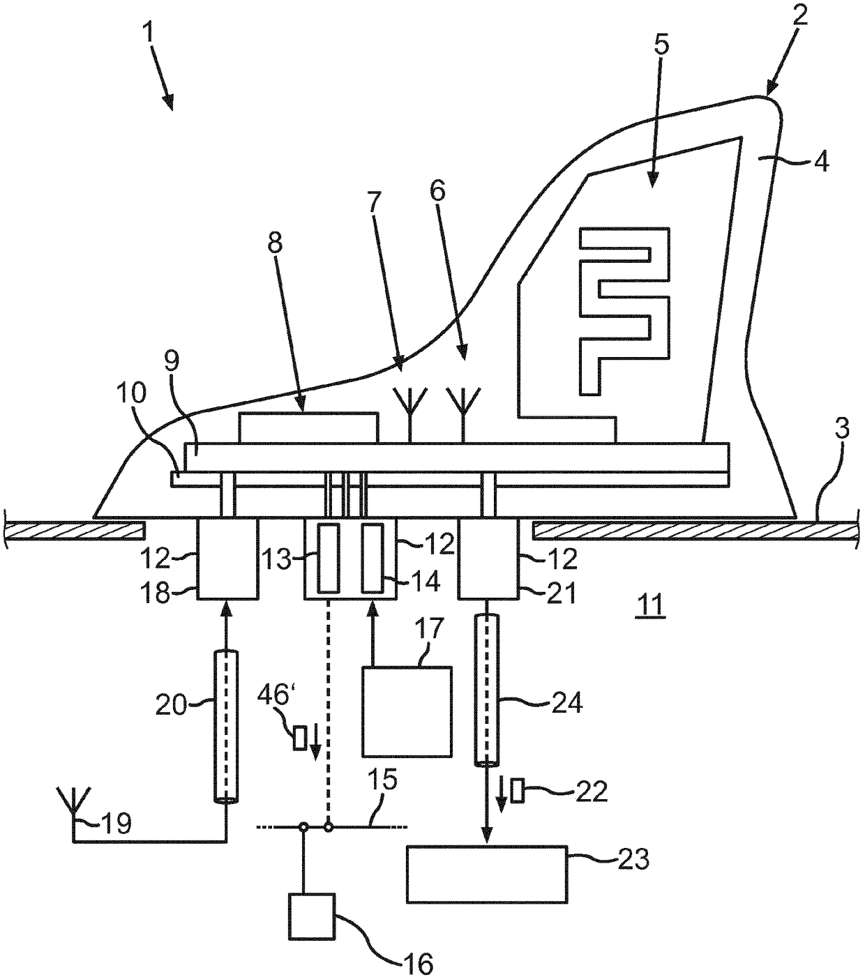
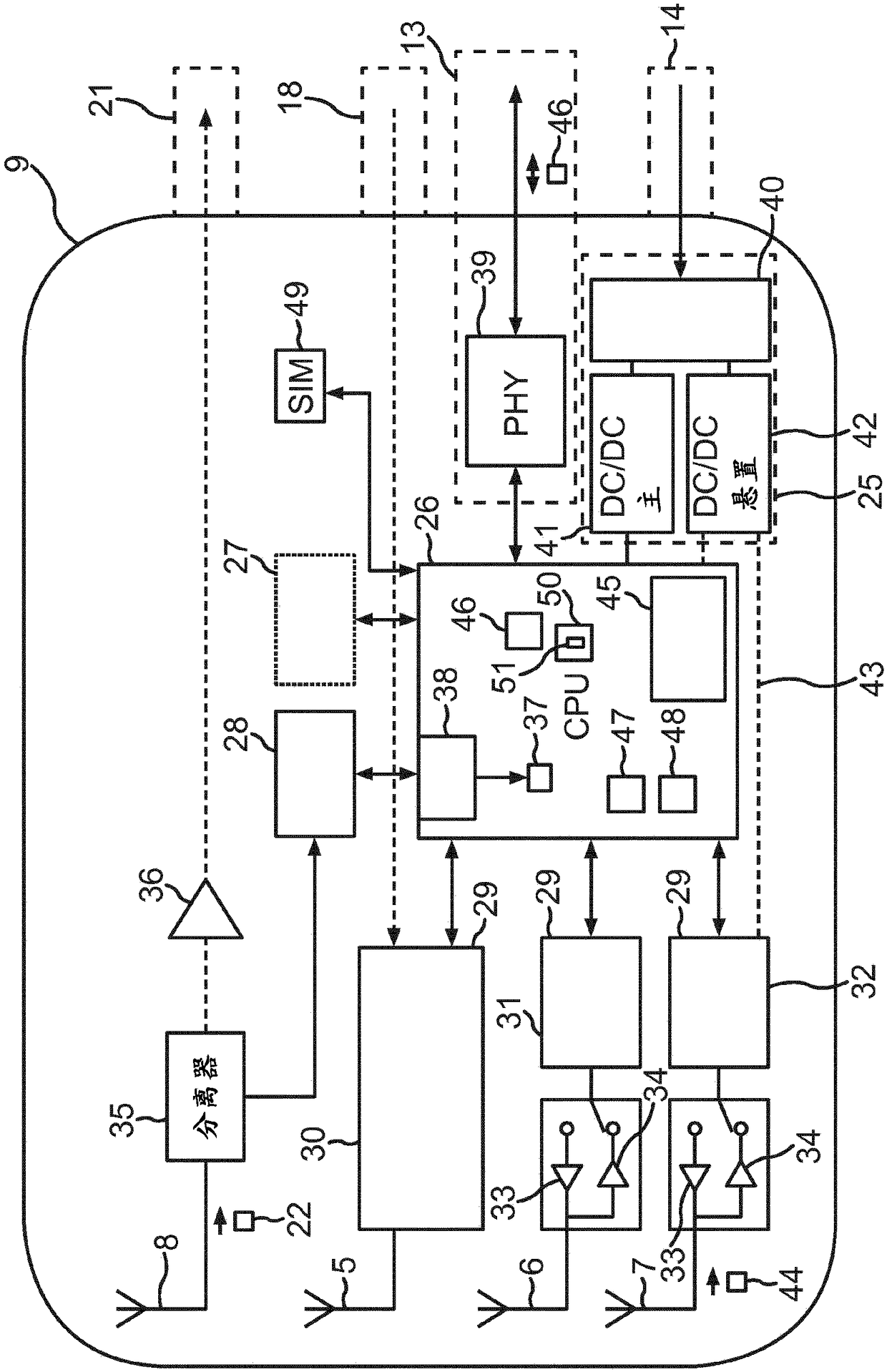
[0035] figure 1 A roof antenna module 2 in a motor vehicle 1 is shown, which can be mounted on a roof 3 . A mobile radio antenna 5 , two short-range antennas 6 , 7 and a GNSS reception antenna 8 can be arranged in the housing 4 of the roof antenna module. The housing 4 may have the shape of a hammerhead. The antennas 5 to 8 can be arranged, for example, on a printed circuit board 9 . The schematic circuit diagram of circuit board 9 is in figure 2 shown in .

[0036] The printed circuit board 9 can have a shielding 10 , by means of which the antenna signals of the antennas 5 to 8 can be prevented from radiating into the vehicle interior 11 . The printed circuit board 9 can be connected to the rest of the motor vehicle 1 via a connection plug or socket 12 . The connection socket 12 can be provided with a bus connection 13 and a power supply connection 14 for power supply. The roof antenna module 2 can be connected to a communication bus 15 of the motor vehicle via a bus c...


PUM


Abstract

The invention relates to a roof antenna module (2) and a method for operating the roof antenna module (2), wherein by means of a communication control unit (26) of the roof antenna module (2) at leastone transceiver (29) of the roof antenna module (2) is coupled to at least one bus connection (13) of the roof antenna module (2) and communication messages (46) are transmitted between the at leastone transceiver (29), on the one hand, and the at least one bus connection (13), on the other. In this context, the intention is to prevent manipulation of the motor vehicle (1) from the outside. Theinvention provides that by means of a filter device (50) of the communication control unit (26) a control instruction (46') which is received by radio from outside the motor vehicle (1) via the at least one transceiver (29) and addressed to a bus user (16) of a communication bus (15) connected via the at least one bus connection (13) is passed on to the at least one bus connection (13) only if thecontrol instruction (46') satisfies a predetermined safety criterion (51).

Description

technical field [0001] The invention relates to a roof antenna module for arrangement on the roof of a motor vehicle. At least one transceiver with a corresponding antenna and at least one bus connection for connecting the roof antenna module to a corresponding digital communication bus of the motor vehicle are provided by the roof antenna module. The at least one transceiver and the at least one bus connection are coupled via a communication control unit, which can transmit communication messages between the at least one transceiver and the at least one bus connection. The invention also includes a motor vehicle with a roof antenna module and a method for operating the roof antenna module. Background technique [0002] It is known from the prior art to integrate a microcontroller into the roof antenna module in order to transmit communication messages between the transceiver and the communication bus. An antenna module is known for this purpose from EP 1 903 632 A1, which...

Claims


Application Information

Patent Timeline
Patent Type & Authority Applications(China)
IPC IPC(8): B60R25/00H04L9/00
CPCB60R16/023H01Q1/3275H04L63/0227H01Q21/28H04W52/0229Y02D30/70H04L67/565H01Q1/283H04L9/0816H04L63/0254
Inventor A·帕普A·波尔J·什佩尔
Owner AUDI AG
Why Eureka
Try Eureka