
Root ventilation flowerpot

A flowerpot and root technology, applied in the field of root ventilation flowerpots, can solve the problems of inability to discharge soil moisture, air circulation, and influence on plant production, and achieve the effect of smooth air, smooth air for a long time, and increased oxygen content

Inactive Publication Date: 2018-08-24
HANGZHOU XIAOCHENG IND DESIGN CO LTD
View PDF0 Cites 0 Cited by
  • Summary
  • Abstract
  • Description
  • Claims
  • Application Information

AI Technical Summary

Problems solved by technology

However, the air in the soil of this flowerpot does not circulate, and the moisture in the soil cannot be completely discharged, which will still affect the production of plants.

Method used


Image

  • Root ventilation flowerpot
  • Root ventilation flowerpot
  • Root ventilation flowerpot

Examples


Embodiment 1

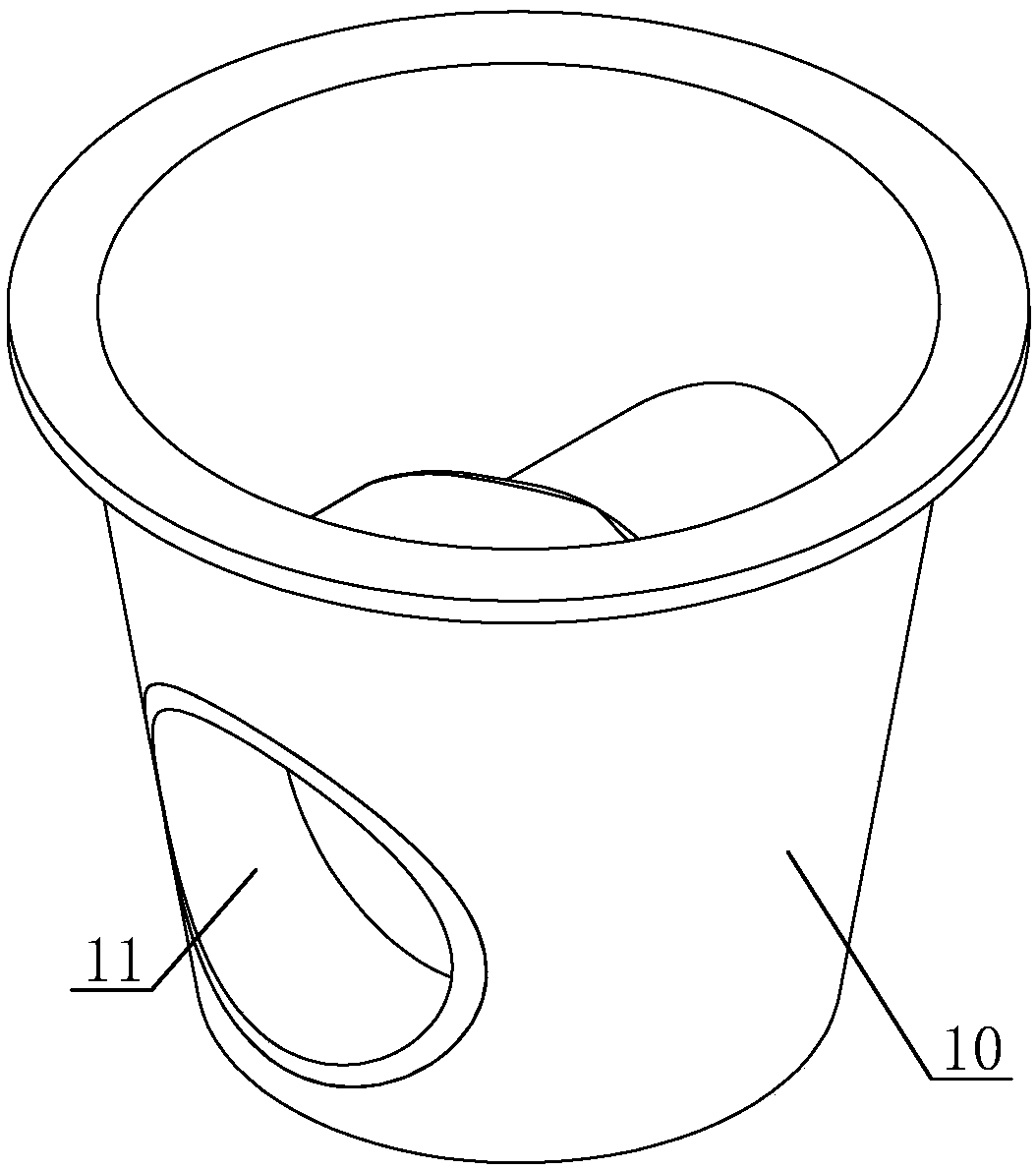
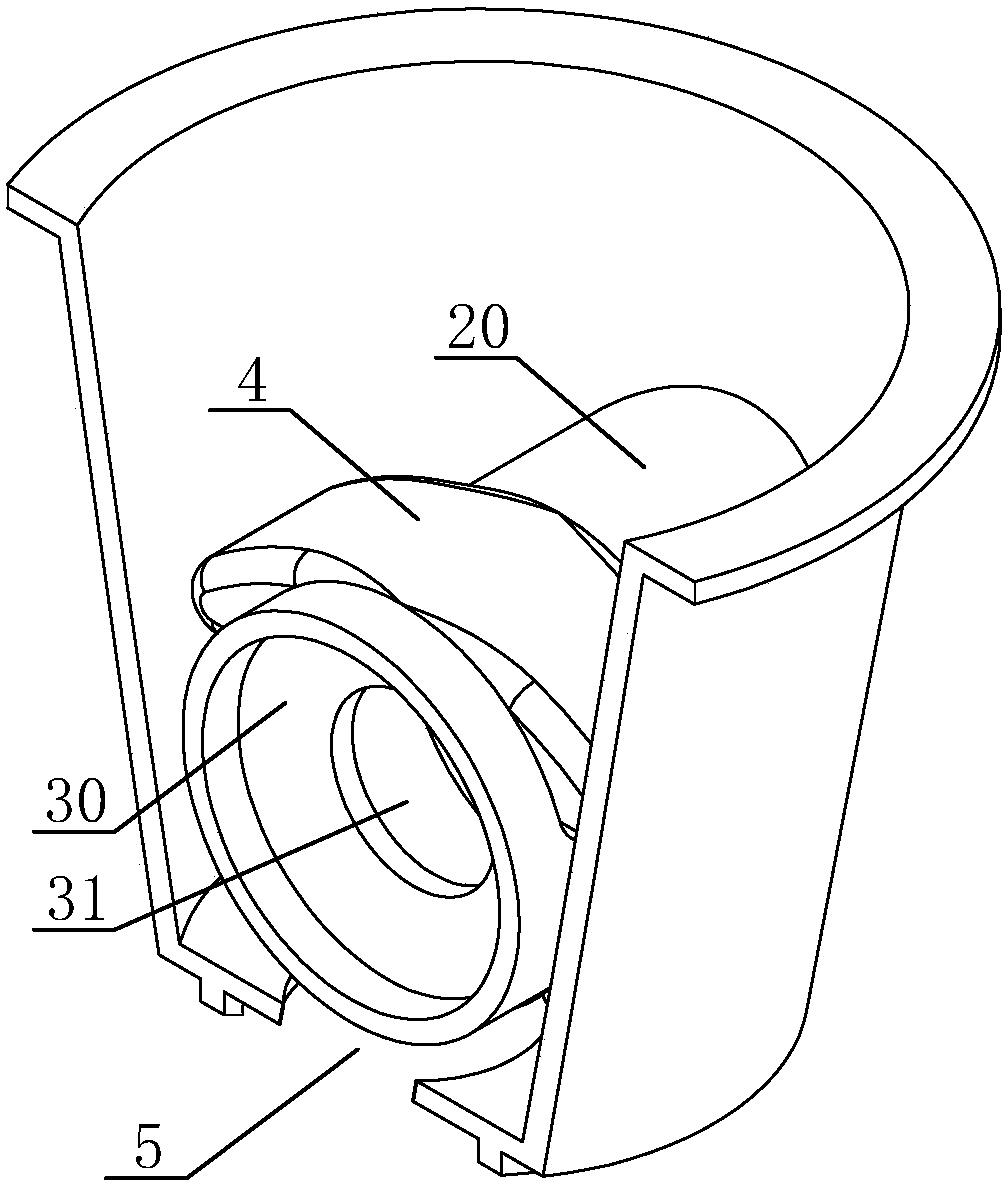
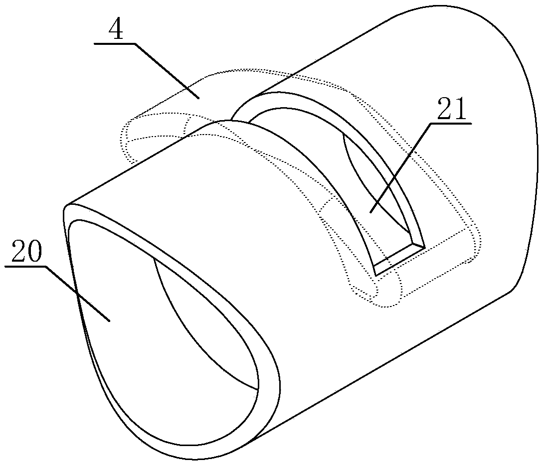
[0027] Such as Figures 1 to 5 The root ventilated flower pot shown includes a pot body 10, and two air inlets 11 for gas entering the pot body 10 are provided on the pot body 10, and the two air inlets 11 are symmetrically arranged on the side wall of the pot body 10, and the two Two air inlets 11 are connected by vent pipe 20, and the middle part of vent pipe 20 is provided with the vent 21 that is used for gas circulation, and vent 21 is positioned at the upper surface of vent pipe 20, and vent pipe 20 is provided with two windshields 30 The two windshields 30 are located on both sides of the air vent 21, the windshields 30 are provided with ventilation holes 31 for ventilation, and the top of the air vent 21 is provided with a top cover 4 for shielding.

[0028] After the plants are planted in the flowerpot of this embodiment, the gas in the air enters the ventilation pipe 20 from the air inlets 11 on both sides of the pot body 10, and the gas on one side passes through th...

Embodiment 2

[0032] as attached Figure 6 And attached Figure 7 Shown is the schematic structural view of the vent pipe 20 in this embodiment 2, and the difference from the embodiment is that in this embodiment, the windshield 30 is located on the upper part of the pipe wall in the vent pipe 20, and the vent pipe 20 is also provided with a A deflector 32 , the deflector 32 is located in the middle of the two windshields 30 , and the deflector 32 is located at the lower part of the pipe wall in the ventilation pipe 20 . Gas enters the ventilation pipe 20 from the air inlet 11 of the flower pot, and the windshield is relatively obliquely arranged in the ventilation pipe 20, and the angle formed between the windshield 30 and the side of the ventilation pipe 20 provided with the ventilation opening 21 is less than 90 degrees . Under the action of the inclined wind deflector 30, the gas is slightly gathered, wherein, the deflector 32 is perpendicular to the pipe wall of the vent pipe 20, and...


PUM


Abstract

The invention discloses a root ventilation flowerpot comprising a pot body; two air inlets for allowing gas to enter the pot body are formed in the pot body and are symmetrically arranged in the sidewalls of the pot body; the two air inlets communicate with each other by a ventilation pipe; a ventilation opening for circulating the gas is formed in the middle of the ventilation pipe and is located in the upper surface of the ventilation pipe; the ventilation pipe is internally provided with two wind shields located at two sides of the ventilation opening; ventilation holes for ventilating andcirculating the gas are formed in the wind shields; and a top cover for shielding is arranged above the ventilation opening. By using the root ventilation flowerpot, the roots of plants can be ventilated, the oxygen content of soil can be increased, and the plants can be kept to grow normally.

Description

technical field [0001] The invention relates to the field of flowerpots, in particular to a root-ventilated flowerpot. Background technique [0002] With the improvement of people's demand for quality of life, planting plants has gradually become a part of people's life. Flower pots are necessary for planting plants. Depending on the plants to be planted, the style, size or material of the flower pots will be different. In the process of planting plants, there is often a phenomenon of overwatering. When the plants are overwatered, the phenomenon of hypoxia and root rot in the soil will affect the growth of the plants. [0003] At present, many flowerpots have also considered the above-mentioned water accumulation problem, and a water outlet hole has been provided at the bottom of the flowerpot to discharge excessive water from the bottom of the flowerpot. However, the air in the soil of the flower pot does not circulate, and the moisture in the soil cannot be completely di...

Claims


Application Information

Patent Timeline
Patent Type & Authority Applications(China)
IPC IPC(8): A01G9/02
CPCA01G9/02
Inventor 李颖
Owner HANGZHOU XIAOCHENG IND DESIGN CO LTD
Learn More