[0008] The present invention is directed to an ion shower
system for use in implantation of ions into a workpiece. The system is particularly advantageous for use in SIMOX applications, wherein a
high oxygen fraction and high beam current uniformity is desired.
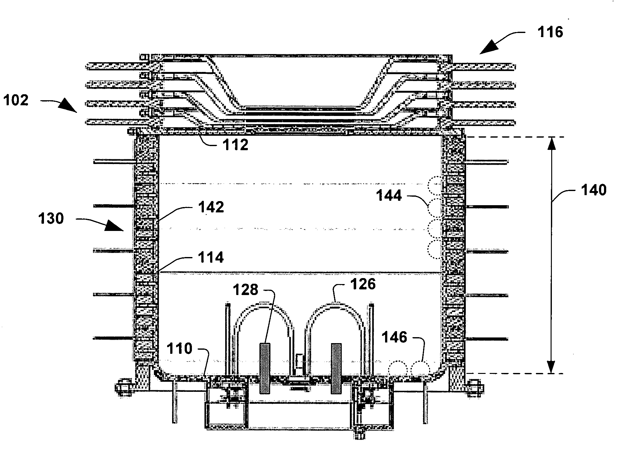
[0009] According to one aspect of the present invention, the ion shower system comprises a
plasma source associated with a chamber. The system further comprises a workpiece support structure associated with a top portion of the chamber, wherein the workpiece support structure is operable to secure a workpiece such as a 300 mm
silicon wafer. The support structure secures the workpiece such that an implantation surface thereof is oriented downward toward the extraction assembly. The
plasma source receives an input source gas (e.g.,
oxygen) and generates a plasma using, for example, RF power. The source and / or chamber are configured such that the generated plasma is azimuthally symmetric within the chamber. The extraction assembly is operable to extract the uniform plasma vertically toward the secured workpiece for implantation thereof. The upside-down design advantageously facilitates reduced
contamination since any contaminants suspended within the plasma fall away from the workpiece upon a deactivation of the plasma. The configuration also advantageously facilitates use of evaporative cooling of the workpiece by configuring an evaporative cooling structure on a top portion of the workpiece support structure, wherein such cooling can be provided in a spatially uniform manner across the workpiece.
[0011] According to still another aspect of the present invention, the ion shower chamber comprises a radial confinement system operable to radially confine the plasma within the chamber. The confinement system, in one example, comprises a magnetic device that generates multi-cusp magnetic fields that serve to prevent the plasma from reaching the chamber sidewalls. In one example, the magnetic device comprises a plurality of independently drivable coils that permit the strength of resulting multi-cusp magnetic fields to be individually controlled for tuning. The confinement system aids in the generation and maintenance of azimuthally symmetric plasma within the chamber, which advantageously facilitates uniform beam current at the workpiece.
[0012] According to yet another aspect of the present invention, the ion shower system comprises an extraction assembly that comprises a multi-
electrode arrangement. A first
electrode, a plasma
electrode, is associated with the chamber and is biased at the same potential as the plasma. The plasma electrode has a plurality of extraction apertures within an extraction region, however, due to the high-density plasma within the chamber, the plasma electrode may have a transparency of as low as 10%. A second electrode, an extraction electrode, is biased negatively with respect to the plasma electrode to form an electrostatic field therebetween and extract positive ions from the chamber. The extraction electrode has a plurality of extraction apertures associated therewith that are aligned substantially with respect to the extraction apertures in the plasma electrode. The extraction electrode further comprises a plurality of interstitial pumping apertures that serve to pump excess neutral source gas therethrough and substantially reduce a pressure associated with the extraction assembly. The reduced pressure improves system reliability by reducing discharges within the chamber due to increased pressure.
[0013] The pattern of extraction electrodes may be spatially uniform or alternatively may vary to provide compensation for any plasma non-uniformities. For example, if the
plasma density within the chamber decreases slightly azimuthally (about the periphery of the chamber), the extraction aperture density can be increased peripherally to provide compensation, thereby further improving beam current uniformity at the workpiece.
[0014] According to still another aspect of the present invention, the ion shower system comprises an RF antenna system for generating a plasma within the system chamber. A neutral source gas, for example, oxygen, is injected into the chamber. The RF antenna system produces RF electric fields that excite charged particles in the chamber that cause a plasma to be generated due to collisions of the accelerated charged particles with the neutral source gas atoms. The antenna system comprises a plurality of conductive
loop antenna segments serially coupled together through capacitors. The arrangement reduces an undesirable non-uniform capacitive field component by a factor of N, wherein N is the number of conductive
loop antenna segments. The reduction in the capacitive field components advantageously facilitates an improvement in plasma uniformity within the chamber. The plurality of conductive loop segments preferably are configured in an azimuthally symmetric arrangement such that, to the extent that any non-uniformity exists for each segment, such non-uniformity is itself azimuthally symmetric within the chamber.

