Clamp suitable for pump body

A fixture and pump body technology, applied in the field of pump processing, can solve problems such as long processing time, and achieve the effects of improving processing efficiency, high practical value, and reducing installation difficulty.

Active Publication Date: 2018-08-24
ANHUI CHANGYU PUMP VALVE MFG CO LTD
View PDF8 Cites 1 Cited by
  • Summary
  • Abstract
  • Description
  • Claims
  • Application Information

AI Technical Summary

Problems solved by technology

[0002] Pumps are indispensable in people's lives now, such as fuel pumps, oil pumps, brake master cylinders, brake slave cylinders, water pumps, clutch master cylinders and clutch slave cylinders in automobiles, as well as water pumps, oil pumps and air pumps in daily life. , and various pumps contain a variety of accessories, and the accessories are composed of many parts. Among the various parts of the pump accessories, the pump body has the longest processing time and the most complicated process. During the processing of the pump body, it needs to pass The auxiliary fixture is used to realize the positioning of the pump body, and the smooth and high-precision processing of the pump body is achieved through various auxiliary fixtures for pump body processing. Therefore, the fixture for pump body auxiliary processing plays a vital role in the pump body processing process. function, but currently there are few fixtures on the market that are specially used to assist in the processing of various types of pump bodies. In addition, when the pump body is clamped, various processes need to be performed, and an adaptable fixture is urgently needed

Method used


Image

  • Clamp suitable for pump body
  • Clamp suitable for pump body
  • Clamp suitable for pump body

Examples


Embodiment Construction

[0021] The following are specific embodiments of the present invention and in conjunction with the accompanying drawings, the technical solutions of the present invention are further described, but the present invention is not limited to these embodiments.

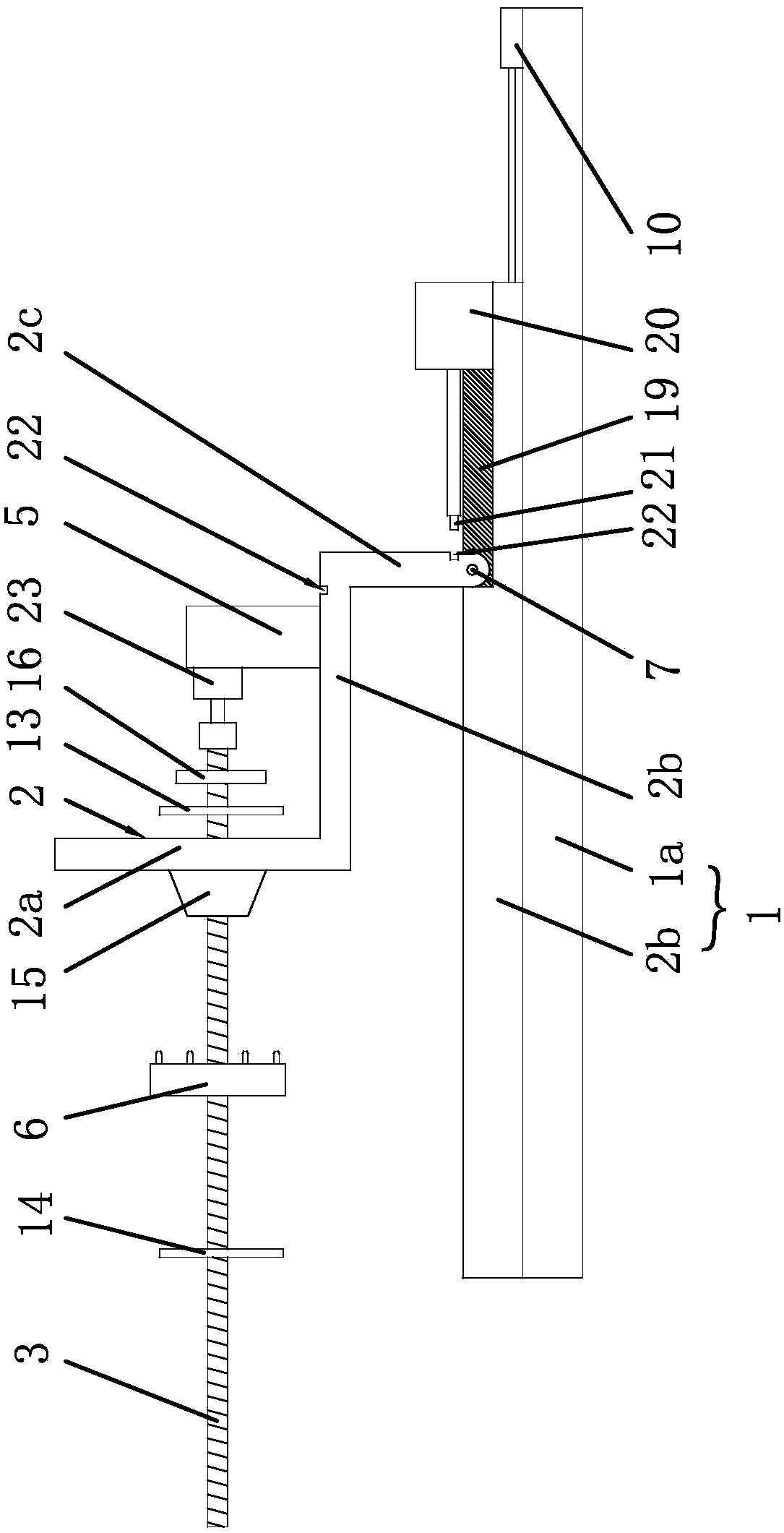
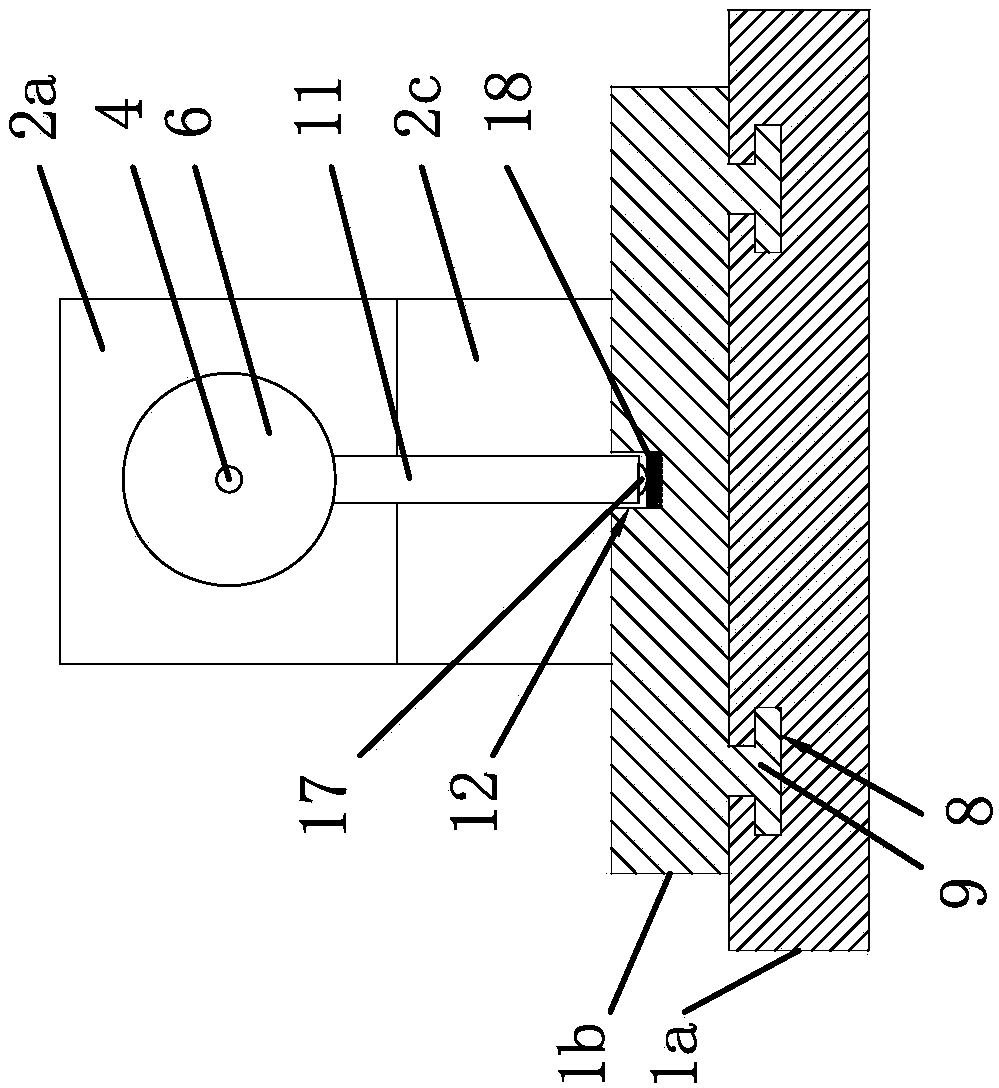
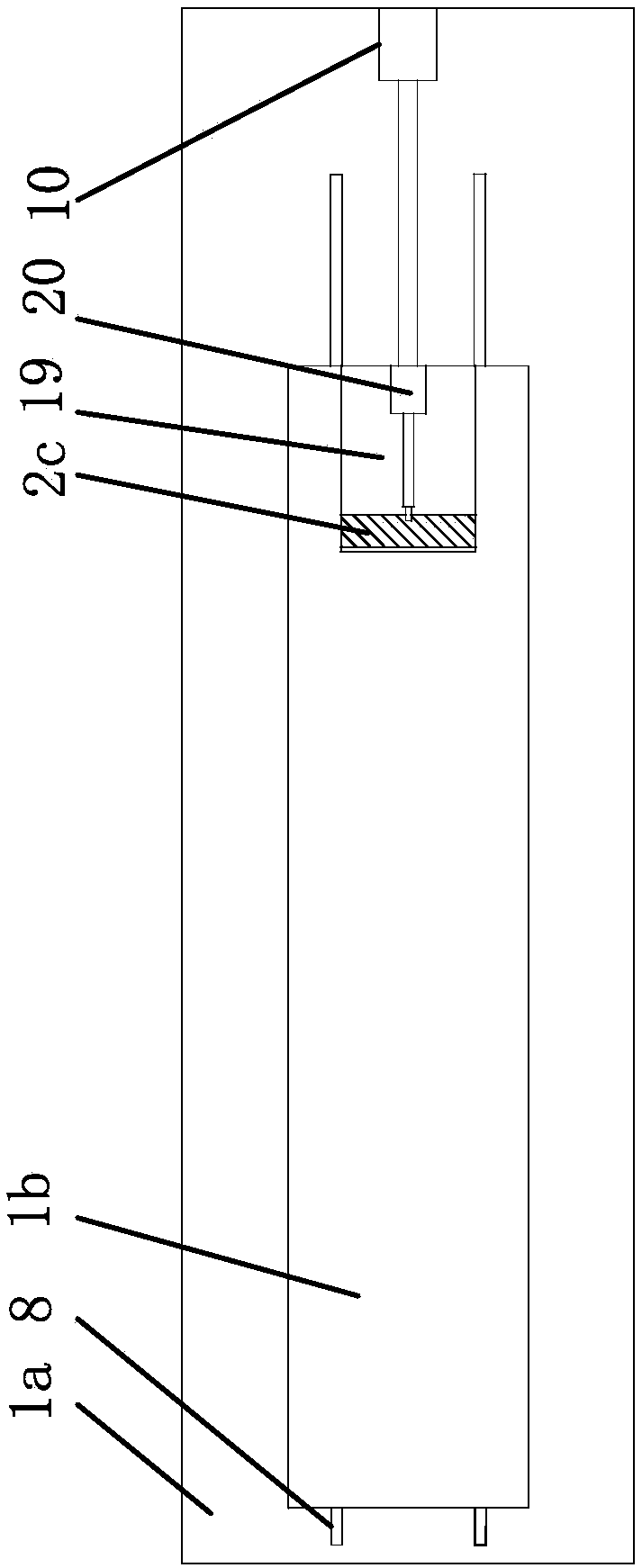
[0022] Such as Figure 1-3 As shown, the fixture suitable for the pump body includes a fixed base 1, a main splint 2 and a connecting screw 3. It is characterized in that the main splint 2 is Z-shaped, and the main splint 2 includes a clamping part 2a, a transition part 2b and a connecting part 2c, the connection part 2c of the main splint 2 is connected to the fixed base 1, the clamping part 2a of the main splint 2 has a through hole 4, the connecting screw 3 penetrates into the through hole 4 of the clamping part 2a, and one side of the connecting screw 3 passes through The shaft coupling is connected with a rotating motor 23, and the rotating motor 23 is fixed to the transition part 2b of the main splint 2 through the m...


PUM


Abstract

The invention provides a clamp suitable for a pump body. The clamp suitable for the pump body comprises a fixed base, a main clamping plate and a connecting screw. The main clamping plate is in a Z shape and comprises a clamping part, a transition part and a connecting part. The connecting part of the main clamping plate is connected to the fixed base. A through hole is formed in the clamping partof the main clamping plate. The connecting screw penetrates through the through hole of the clamping part. A rotary motor is connected to one side of the connecting screw through a coupling and fixedto the transition part of the main clamping plate through a motor installation frame. An auxiliary clamping block is connected to the other side of the connecting screw in a threaded mode. The connecting part is rotatably connected to the fixed base through a rotary shaft. The fixed base comprises a lower base body and an upper base body. A guide sliding groove is formed in the upper end of the lower base body. A guide strip embedded into the guide sliding groove is arranged at the lower end of the upper base body. A push cylinder used for pushing the upper base body to slide is further fixedto one side of the lower base body. The guide sliding groove and the guide strip are arranged so that the pump body can move in the clamping process, and the direction of the pump body can be changedthrough rotation of the connecting part.

Description

technical field [0001] The invention belongs to the technical field of pump processing and relates to a clamp suitable for a pump body. Background technique [0002] Pumps are indispensable in people's lives now, such as fuel pumps, oil pumps, brake master cylinders, brake slave cylinders, water pumps, clutch master cylinders and clutch slave cylinders in automobiles, as well as water pumps, oil pumps and air pumps in daily life. , and various pumps contain a variety of accessories, and the accessories are composed of many parts. Among the various parts of the pump accessories, the pump body has the longest processing time and the most complicated process. During the processing of the pump body, it needs to pass The auxiliary fixture is used to realize the positioning of the pump body, and the smooth and high-precision processing of the pump body is achieved through various auxiliary fixtures for pump body processing. Therefore, the fixture for pump body auxiliary processing...

Claims


Application Information

Patent Timeline
IPC IPC(8): B23Q3/08
CPCB23Q3/08B23Q2703/04
Inventor 王爱军
Owner ANHUI CHANGYU PUMP VALVE MFG CO LTD
Why Eureka
Try Eureka