Workpiece jig cabin-transfer manipulator for vacuum coating machine

A vacuum coating machine and manipulator technology, applied in the field of manipulators, can solve the problems of high difficulty in design and manufacture, large volume and high cost, and achieve the effects of low maintenance cost, simple and compact structure, and cost reduction.

Pending Publication Date: 2020-09-25
DONGGUAN HUICHENG VACUUM TECH
View PDF0 Cites 4 Cited by
  • Summary
  • Abstract
  • Description
  • Claims
  • Application Information

AI Technical Summary

Problems solved by technology

The former method usually uses the workpiece rack to transfer the whole vehicle, which is faster and more efficient. However, for large workpiece racks, due to their large size and weight, the structural design requirements are higher; the biggest difficulty is the requirements

Method used


Image

  • Workpiece jig cabin-transfer manipulator for vacuum coating machine
  • Workpiece jig cabin-transfer manipulator for vacuum coating machine
  • Workpiece jig cabin-transfer manipulator for vacuum coating machine

Examples


Embodiment Construction

[0033] The technical solutions in the embodiments of the present invention will be clearly and completely described below in conjunction with the accompanying drawings.

[0034] It should be noted that if the embodiment of the present invention involves directional indications (such as up, down, left, right, front, back, top, bottom, inside, outside, vertical, horizontal, vertical, counterclockwise, clockwise, circumferential direction, radial direction, axial direction...), the directional indication is only used to explain the relative positional relationship, movement conditions, etc. When a change occurs, the directional indication changes accordingly.

[0035] The invention provides a vacuum coating machine workpiece jig transfer cabin manipulator.

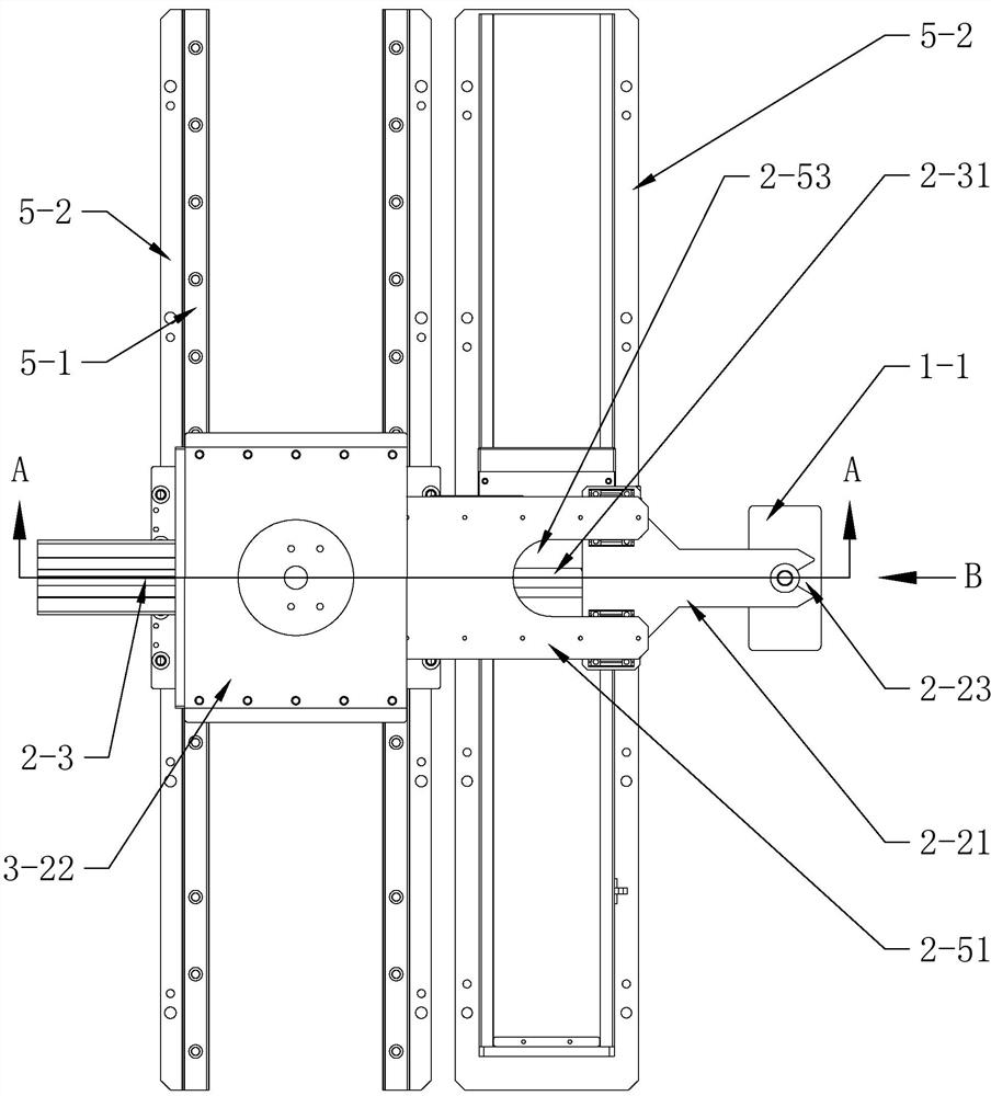
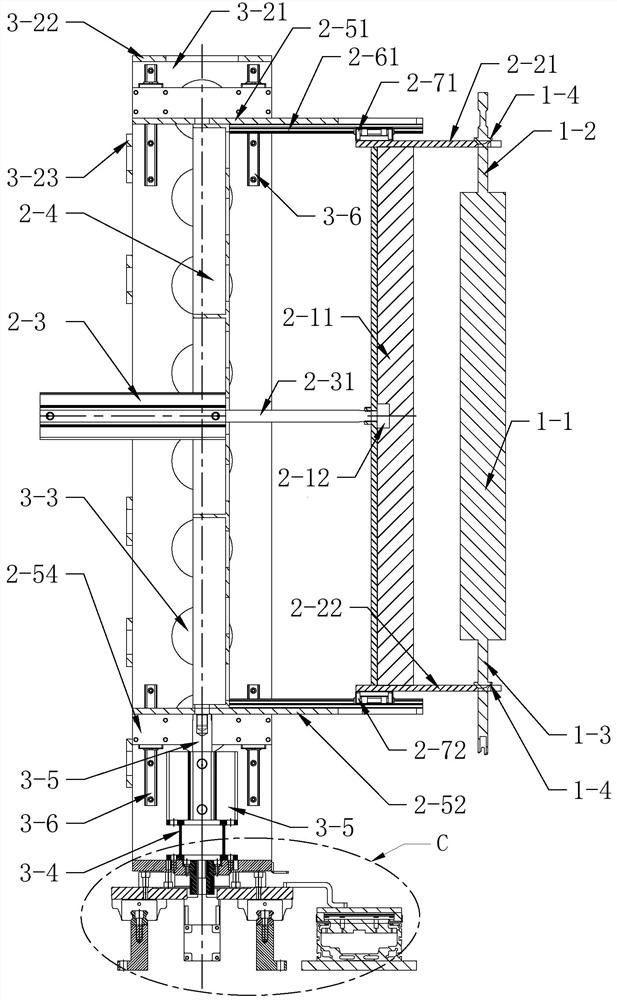
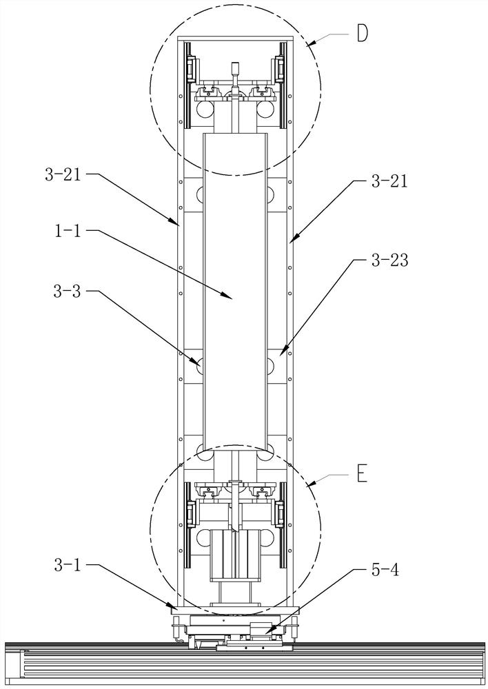
[0036] Such as Figure 1 to Figure 8As shown, the manipulator for workpiece fixture transfer includes a clamping mechanism for clamping the fixture 1, and a telescopic mechanism and a lifting mechanism for respectively cont...


PUM


Abstract

The invention discloses a workpiece jig cabin-transfer manipulator for a vacuum coating machine. Through the movement functions of front-rear extending and retracting, up-down ascending and descending, rotating and horizontal moving along a guide rail of the manipulator, bayonets of an upper claw and a lower claw and jigs are designed to correspond to clamping blocks on inserting rods, through powerful support provided by a supporting plate between the upper claw and the lower claw and bearing of a main frame and a base of the main frame, a single large jig is clamped, the single large jig canbe accurately transferred to a certain functional cabin to be mounted, and then the manipulator is returned for clamping the next jig; the manipulator for the vacuum coating machine is suitable for the single-hung jigs with the large size or the high weight, as for the type of coating machine, a whole workpiece frame does not need to be overall conveyed, thus an oversized cabin door does not needto be specifically designed, and the construction cost is lowered; and as for a cabin-transfer method for the jigs, the number of times of vacuum breaking is effectively decreased, the jigs are heated in a heating cabin and then distributed to coating cabins of different film systems for simultaneous coating of the different film systems, and thus the processing efficiency is greatly improved.

Description

technical field [0001] The invention relates to a manipulator, in particular to a multi-chamber manipulator for workpiece fixture transfer of a vacuum coating machine. Background technique [0002] The traditional single-chamber vertical vacuum coating machine needs to manually hang the workpieces to be coated on the fixture (or the hanging plate or hanging rod of the workpiece rack) outside the furnace, and then manually hang the fixtures into the furnace one by one. On the workpiece rack, carry out coating. [0003] In recent years, in order to improve the coating efficiency, a multi-chamber vacuum coating machine has appeared. The cabin layout includes the following two types: the first one is a linear conveyor guide cabin in the center, and the front and rear ends are respectively the feed cabin and the discharge cabin. Multiple functional cabins are arranged on the left and right sides; the other is a center-symmetrical satellite layout, in which multiple functional ca...

Claims


Application Information

Patent Timeline
IPC IPC(8): B25J9/02B25J15/08C23C14/56
CPCB25J9/02B25J15/08C23C14/568
Inventor 李志方陈思陸创程冯晓庭
Owner DONGGUAN HUICHENG VACUUM TECH
Why Eureka
Try Eureka