Spring grinding mechanism

A grinding and combination mechanism technology, applied in the field of spring grinding, can solve the problems of adjusting the bearing interference, affecting the spring grinding accuracy, affecting the vertical accuracy of the spring, etc., so as to improve the grinding accuracy and stability. The effect of low cost and high production efficiency

Inactive Publication Date: 2018-08-24
JIANGSU XIANGYING HARDWARE SPRING CO LTD
View PDF0 Cites 0 Cited by
  • Summary
  • Abstract
  • Description
  • Claims
  • Application Information

AI Technical Summary

Problems solved by technology

Therefore, produce three aspects consequences like this: 1), whole disk spring only has about 17% to grind on emery wheel plane simultaneously, and production efficiency is low
2) The grinding amount of each spring is only 17% of the downward movement of the grinding wheel when the grinding disc rotates one circle, and there is still 83% of the moving amount. The spring is actually outside the grinding wheel and has not been ground, which is unreasonable. An unreasonable consequence is that because of the sudden grinding amount at point a of the grinding wheel is large, point a wears quickly, point b wears slowly, and point c basically does not participate in grinding
Therefore, the final shape of the end face of the grinding wheel becomes a truncated cone, such as image 3 , which seriously affects the vertical accuracy of spring grinding
3) Because when the two grinding wheels are grinding, only the position that coincides with the grinding disc is stressed, and the grinding amount at point a of the grinding wheel is large, that is, the main grinding force is at this place, and the axial component of the above grinding force is combined. Therefore, the grinding wheel shaft and the grinding wheel disc have to bear a large bending moment, resulting in a large geometric deformation, which is more obvious for heavy grinding springs, which seriously affects the spring grinding accuracy
[0005] Second, due to the unevenness of the grinding wheel during grinding, the end face of the spring is actually a plane that is not perpendicular to the axis of the spring, so the spring cannot rotate during the entire grinding process from point a to point c, so the precision of the spring after grinding is not high
This is not only difficult to find such a mechanic, but also very troublesome to adjust the interference of the bearing

Method used


Image

  • Spring grinding mechanism
  • Spring grinding mechanism
  • Spring grinding mechanism

Examples


Embodiment Construction

[0037] The present invention will be further described below in conjunction with the accompanying drawings and specific embodiments.

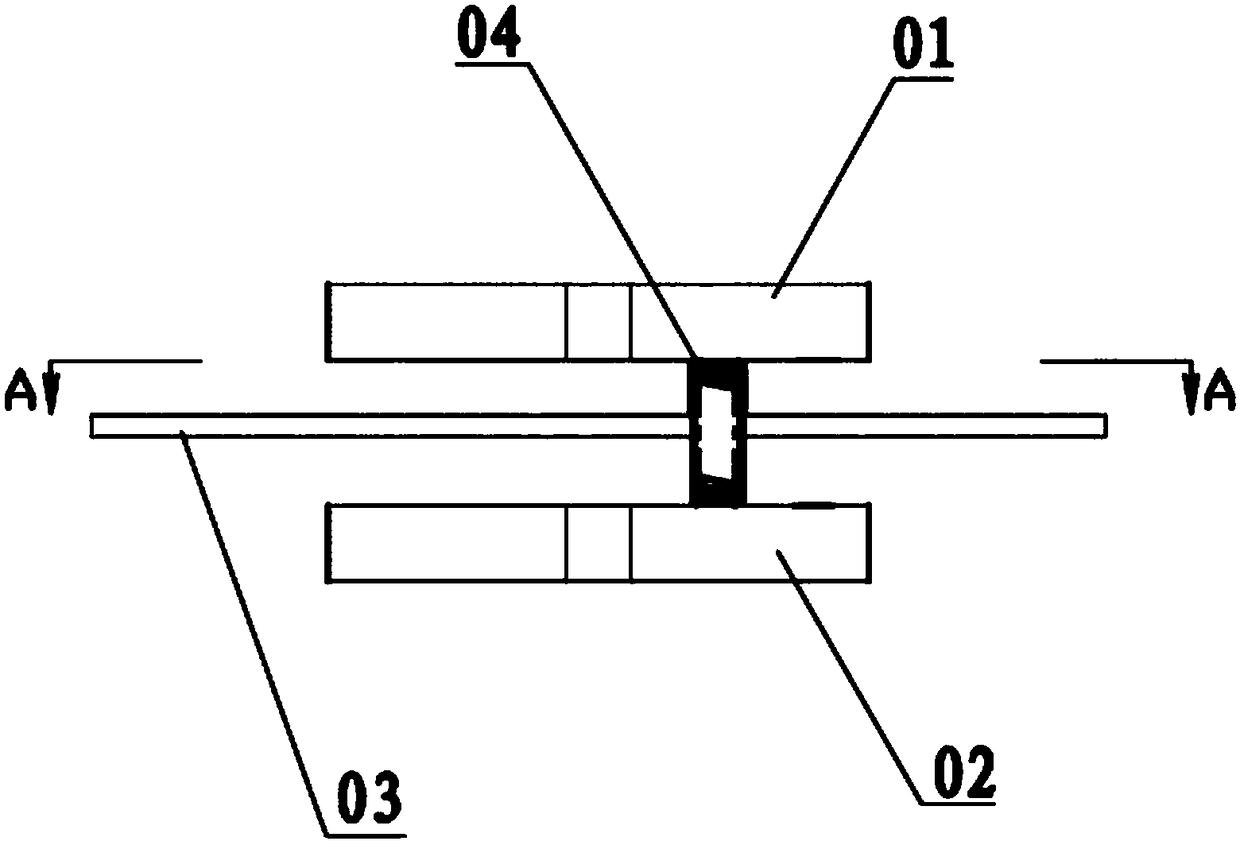
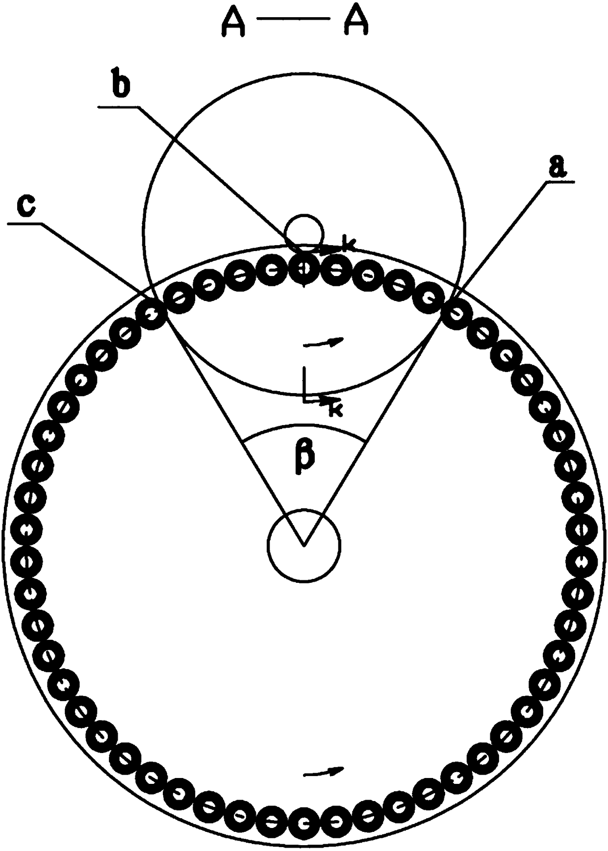
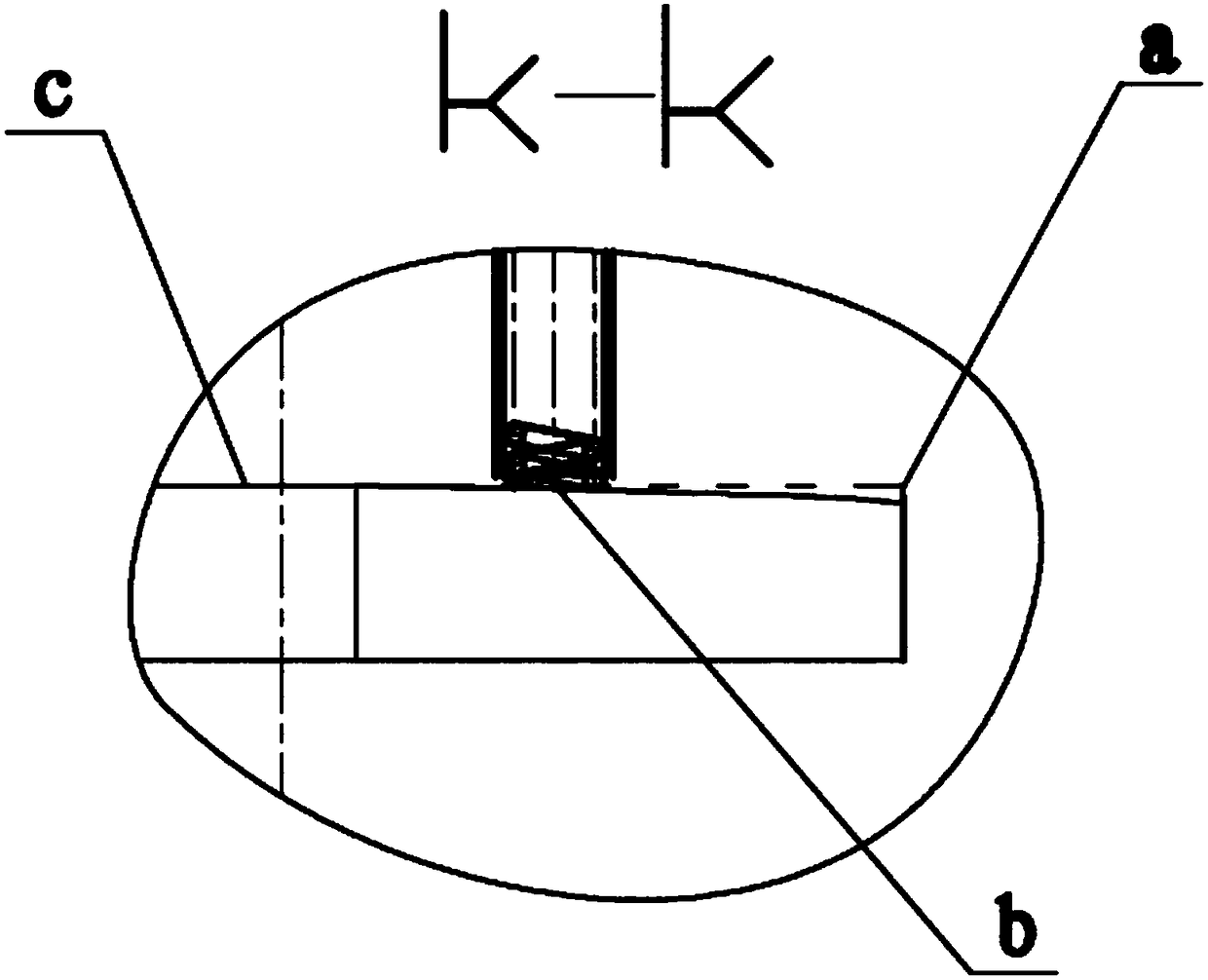
[0038] As shown in the figure, a kind of spring grinding method disclosed by the present invention and its mechanism include an upper grinding wheel 1 and a lower grinding wheel 2. At least one of the upper and lower grinding wheels 2 is composed of an inner grinding wheel 21 and an outer grinding wheel 24. In this implementation In the example, the upper grinding wheel 1 is selected as an integral structure, the lower grinding wheel 2 is composed of an inner grinding wheel 21 and an outer grinding wheel 24, the outer diameter of the inner grinding wheel 21 is slightly smaller than the inner diameter of the outer grinding wheel 24, and the inner grinding wheel 21 is sleeved in the outer grinding wheel 24. Inner emery wheel 21 is opposite to outer emery wheel 24 rotation direction, and outer emery wheel 24 is identical with upper emery wheel 1 ro...


PUM


Abstract

The invention relates to the field of spring grinding, in particular to a spring grinding mechanism. The spring grinding mechanism comprises an upper grinding wheel, a lower grinding wheel and a grinding disc; the grinding disc is positioned between the upper grinding wheel and the lower grinding wheel; the upper grinding wheel or the lower grinding wheel consists of an inner grinding wheel and anouter grinding wheel; the inner grinding wheel is sleeved with the outer grinding wheel; the inner grinding wheel or the outer grinding wheel is driven through a transmission mechanism; and rotatingdirections of the inner grinding wheel and the outer grinding wheel are opposite. After the spring grinding mechanism is adopted, a spring is grinded in a rotating state, so that the quality and the yield of the grinded spring can be improved, energy conservation and environmental protection are achieved, and the grinding cost is low. The spring grinding mechanism is excellent in stress performance, long in mechanism precision retentivity and high in stability.

Description

technical field [0001] The invention relates to the field of spring grinding, in particular to a spring grinding mechanism. Background technique [0002] At present, the schematic diagram of the basic mechanism of the double-end surface spring grinding machine of the CNC spring grinding machine is as follows figure 1 , figure 2 , this structure is the upper grinding wheel 01, the lower grinding wheel 02, the upper grinding wheel 01 can move up and down, the grinding disc 03 with the spring 04 placed between the end faces of the two grinding wheels, the grinding disc 03 rotates on a fixed axis, the basic working principle is: the grinding disc 03 rotates on a fixed axis, the grinding disc The spring 04 on 03 is driven by the rotation of the grinding disc 03, enters between the end faces of the two grinding wheels from point a, passes through point b to point c, and comes out from between the end faces of the two grinding wheels, the spring 04 continues to be driven by the r...

Claims


Application Information

Patent Timeline
Patent Type & Authority Applications(China)
IPC IPC(8): B24B7/16B24B7/17B24B27/00
CPCB24B7/167B24B7/17B24B27/0076B24B27/0092
Inventor 姚惠彬
Owner JIANGSU XIANGYING HARDWARE SPRING CO LTD
Why Eureka
Try Eureka