Rapid vacuum switching mechanism

A conversion mechanism and vacuum technology, applied in the direction of conveyor objects, transportation and packaging, can solve the problems of poor stability of the suction process, slow suction speed, short service life of the cylinder, etc., to improve production efficiency and product quality, reduce Human and material resources, the effect of improving conversion speed and automation

Pending Publication Date: 2018-08-24
汕头市信力制罐设备有限公司
View PDF0 Cites 0 Cited by
  • Summary
  • Abstract
  • Description
  • Claims
  • Application Information

AI Technical Summary

Problems solved by technology

At present, the conveying mechanism of most automation machinery in machinery factories uses cylinders for material suction, which has a h...

Method used


Image

  • Rapid vacuum switching mechanism
  • Rapid vacuum switching mechanism
  • Rapid vacuum switching mechanism

Examples


Embodiment Construction

[0020] In order to have a further understanding of the purpose, features and functions of the present invention, preferred embodiments are hereby given and described in detail in conjunction with the drawings as follows:

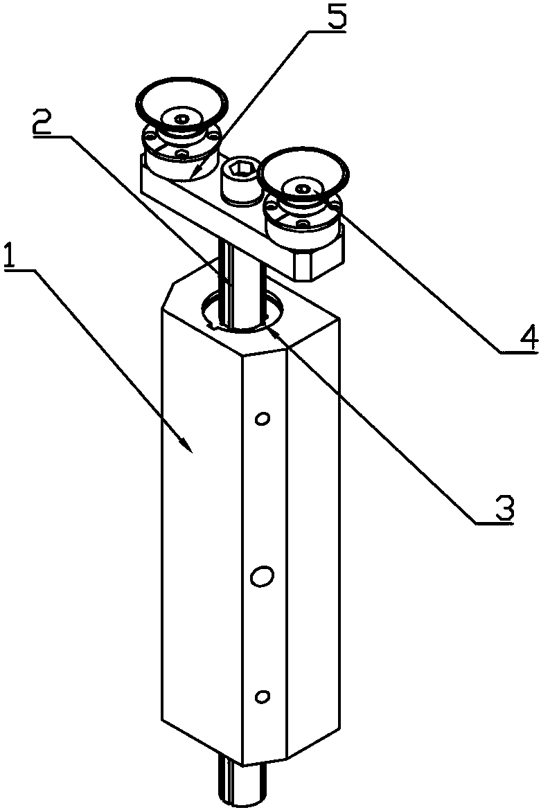
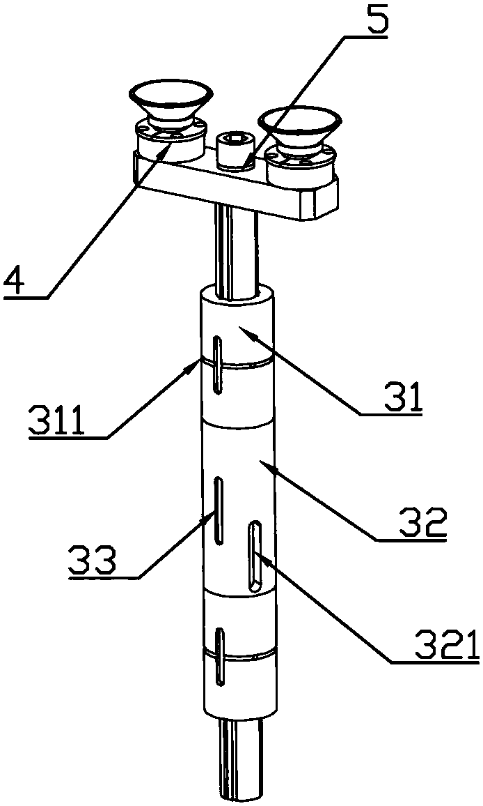
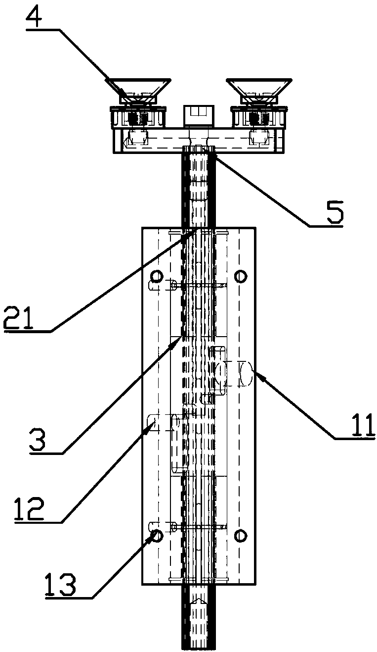
[0021] Figures 1~5 As shown, it is a schematic structural diagram of a preferred embodiment of the present invention. The present invention is a rapid vacuum conversion mechanism, which mainly includes: a guide sleeve seat 1, a guide shaft 2, a guide bearing sleeve 3, a suction cup buffer 4 and a suction cup connection. Rod 5, the guide bearing sleeve 3 is arranged in the guide sleeve seat 1, the guide shaft 2 runs through the guide bearing sleeve 3, the guide shaft 2 drives the guide bearing sleeve 3 to move along the inside of the guide sleeve seat 1, and the top of the guide shaft 2 is connected For the suction cup connecting rod 5, the suction cup buffer 4 is installed on the bottom of the suction cup connecting rod 5, and the guide sleeve seat 1 is pro...


PUM


Abstract

The invention relates to the field of mechanical automation equipment, in particular to a rapid vacuum switching mechanism. A guiding bearing sleeve is arranged in a guiding sleeve seat. A guiding shaft penetrates the guiding bearing sleeve and draws the guiding bearing sleeve to shift along the interior of the guiding sleeve seat. The top of the guiding shaft is connected to a suction disc connecting rod. Suction disc buffer parts are mounted at the bottom of the suction disc connecting rod. The guiding sleeve seat is provided with an air inlet and an air drafting hole. The air inlet and theair drafting hole are formed in the guiding bearing sleeve in a through manner and communicate with the suction disc buffer parts through an inner pipe of the guiding shaft. The rapid vacuum switchingmechanism has the beneficial effects that mechanical type design is adopted for the vacuum switching mechanism so that materials can be rapidly sucked and break away through the suction disc buffer parts; compared with a traditional control air pump, the switching speed of the rapid vacuum switching mechanism is increased, and the automation degree of the rapid vacuum switching mechanism is raised; and thus, manpower and material resources of a manufacturer are reduced, and production efficiency and product quality of the rapid vacuum switching mechanism are greatly improved.

Description

technical field [0001] The invention relates to the field of mechanical automation equipment, in particular to a fast vacuum switching mechanism. Background technique [0002] With the rapid development of economic construction, mechanical automation is very important for an enterprise. At the same time, with the continuous rise of labor costs in recent years, enterprises are also under huge economic pressure. The vacuum conversion mechanism can be used in a variety of automated machinery to complete the suction action of the equipment and improve the conveying speed between processes. The stability and transportation efficiency during suction are the keys to the vacuum conversion mechanism. At present, most of the conveying mechanisms of automated machinery in machinery factories use cylinders for material suction, which has a high equipment failure rate, short service life of cylinders, slow material suction speed, and poor stability of the material suction process. SUMM...

Claims


Application Information

Patent Timeline
IPC IPC(8): B65G47/90
CPCB65G47/90
Inventor 章文献
Owner 汕头市信力制罐设备有限公司
Why Eureka
Try Eureka