Optical cable pay-off device for optical fiber telecommunication construction

A pay-off device and optical cable technology, which is applied in the directions of transportation and packaging, delivery of filamentous materials, thin material processing, etc., can solve problems such as difficult bending of optical cables, long-distance tensioning, and damage to internal optical fibers, etc., to achieve Protect the state of pay-off requirements, reduce labor, and avoid the effects of springback and bending

Pending Publication Date: 2018-08-24
YANGTZE UNIVERSITY
View PDF0 Cites 4 Cited by
  • Summary
  • Abstract
  • Description
  • Claims
  • Application Information

AI Technical Summary

Problems solved by technology

Because the optical cable has steel wires and steel belts to protect the optical fiber inside, the bending elasticity of the optical cable is extremely strong. If the grip is slightly relaxed during traction, the optical cable will be bent, and long-distance tensioning is particularly laborious; especially in cable trenches. It is more difficult to straighten and bend the optical cable, and damage to the internal optical fiber occurs from time to time. At this time, the broken optical cable needs to be cut off and re-laid. Therefore, 3-5 people are required to cooperate during construction, which is not only labor-intensive, but also easy cause economic loss

Method used


Image

  • Optical cable pay-off device for optical fiber telecommunication construction
  • Optical cable pay-off device for optical fiber telecommunication construction
  • Optical cable pay-off device for optical fiber telecommunication construction

Examples


Embodiment Construction

[0024] The present invention will be further described below in conjunction with accompanying drawing:

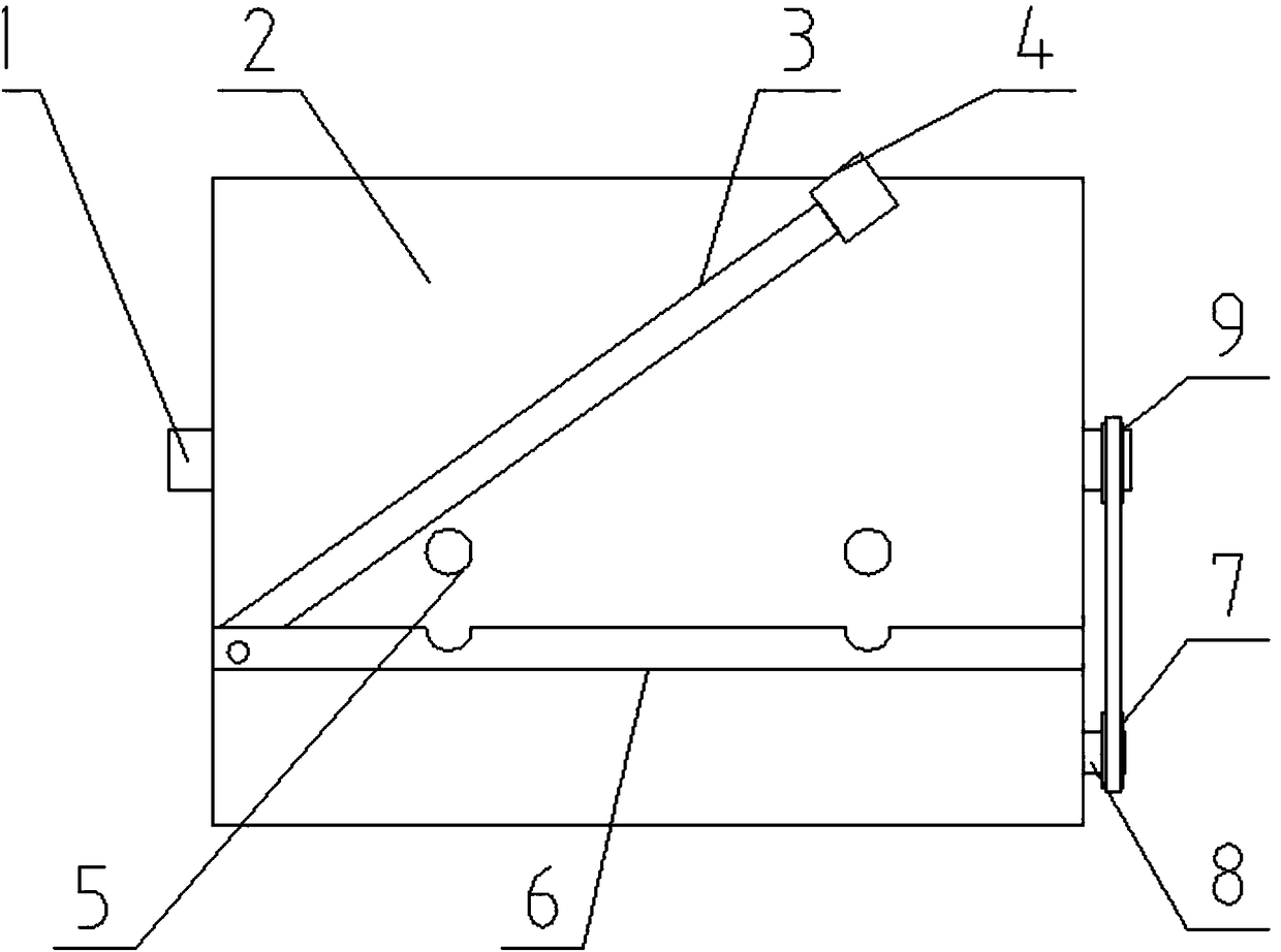
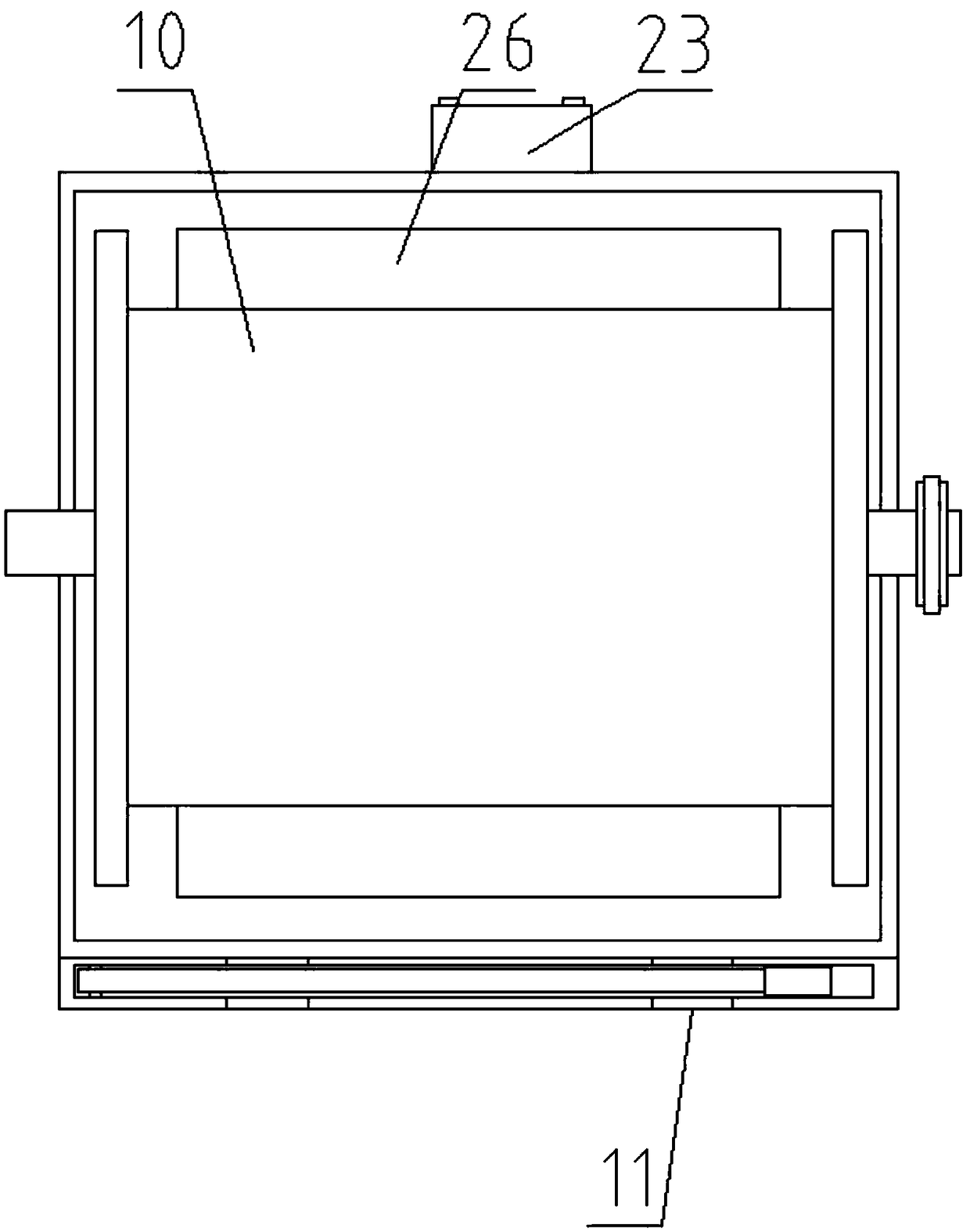
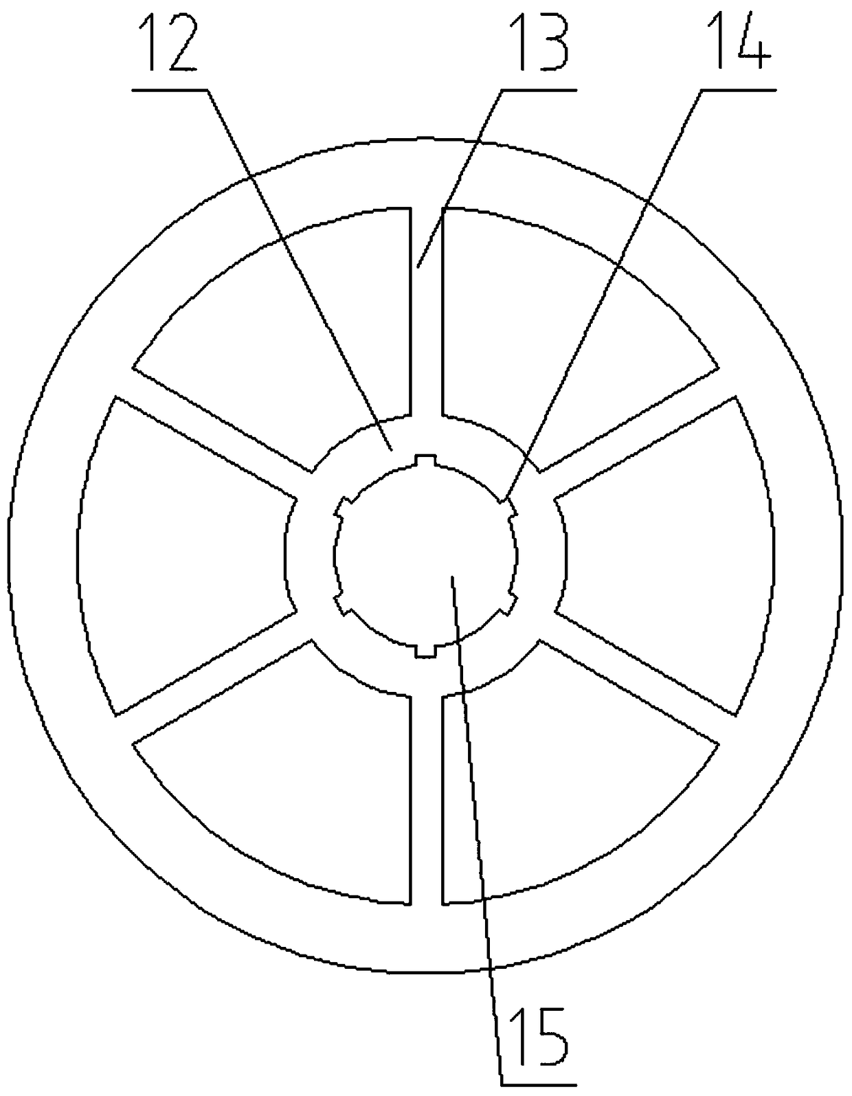
[0025] Such as Figure 1-Figure 5 As shown, an optical cable pay-off device for optical fiber telecommunication construction includes a main shaft 1, a pay-off box 2, a cutter 3, and a mounting frame 21. The main shaft 1 is arranged in the pay-off box 2, and one end of the main shaft 1 is arranged There is a driven wheel 9, a reel 10 is arranged on the outer side of the main shaft 1, a hub 12 is arranged at both ends of the reel 10, a support frame 13 is arranged on the outer side of the hub 12, and a central hole 15 is arranged on the inner side of the hub 12, The outer side of the central hole 15 is provided with a slotted hole 14, and the bottom of the reel 10 is provided with a motor 26, and one end of the motor 26 is provided with a transmission shaft 8, and one end of the transmission shaft 8 is provided with a driving wheel 7. A control box 23 is arranged at the rea...


PUM

PropertyMeasurementUnit
diameteraaaaaaaaaa
diameteraaaaaaaaaa

Abstract

The invention discloses an optical cable pay-off device for optical fiber telecommunication construction. The optical cable pay-off device comprises a spindle, a pay-off box, a cutting knife and a mounting frame. The spindle is arranged in the pay-off box. A driven wheel is arranged at one end of the spindle. A winding wheel is arranged on the outer side of the spindle. Wheel hubs are arranged atthe two ends of the winding wheel. Supporting frames are arranged on the outer side of the wheel hubs. Center holes are formed in the inner sides of the wheel hubs. Slotted holes are formed in the outer sides of the center holes. A motor is arranged under the winding wheel. A transmission shaft is arranged at one end of the motor. A driving wheel is arranged at one end of the transmission shaft. Acontrol box is arranged on the rear portion of the pay-off box. A forward rotation button is arranged on the surface of the control box. A reverse rotation button is arranged on one side of the forward rotation button. The optical cable pay-off device has the beneficial effects that workloads of manual pay-off are reduced, the pay-off efficiency is improved, meanwhile, and rebound and bending ofoptical cables are avoided. The pay-off required state is protected, economic losses are reduced, meanwhile, the optical cable pay-off device is provided with a cutting device, and cutting is facilitated.

Description

technical field [0001] The invention relates to the technical field of optical cable construction, in particular to an optical cable pay-off device for optical fiber telecommunication construction. Background technique [0002] In the power communication construction project, the optical cable is usually paid out by manually holding the free end of the optical cable along the cable trench. Because the optical cable has steel wires and steel belts to protect the optical fiber inside, the bending elasticity of the optical cable is extremely strong. If the grip is slightly relaxed during traction, the optical cable will be bent, and long-distance tensioning is particularly laborious; especially in cable trenches. It is more difficult to straighten and bend the optical cable, and damage to the internal optical fiber occurs from time to time. At this time, the broken optical cable needs to be cut off and re-laid. Therefore, 3-5 people are required to cooperate during construction...

Claims


Application Information

Patent Timeline
Patent Type & Authority Applications(China)
IPC IPC(8): B65H57/14B65H49/34B65H67/02B65H49/30B21F11/00
CPCB65H57/14B21F11/00B65H49/30B65H49/34B65H67/02B65H2701/32
Inventor 黄春雄
Owner YANGTZE UNIVERSITY
Why Eureka
Try Eureka