
Lifting device of automatic equipment

A technology of automation equipment and lifting device, applied in glass manufacturing equipment, glass cutting devices, manufacturing tools, etc., can solve problems such as the inability to achieve stable lifting

Inactive Publication Date: 2018-08-24
常熟梁方智能技术有限公司
View PDF0 Cites 0 Cited by
  • Summary
  • Abstract
  • Description
  • Claims
  • Application Information

AI Technical Summary

Problems solved by technology

However, although the existing automatic cutting equipment can automatically realize the large-scale movement of the device, it needs to flexibly change the position of the cutting equipment and carry out lifting, which cannot meet the requirements of stable lifting. Therefore, we propose an automated The lifting device of the equipment to solve the above problems

Method used


Image

  • Lifting device of automatic equipment
  • Lifting device of automatic equipment
  • Lifting device of automatic equipment

Examples


Embodiment Construction

[0017] The following will clearly and completely describe the technical solutions in the embodiments of the present invention with reference to the accompanying drawings in the embodiments of the present invention. Obviously, the described embodiments are only some, not all, embodiments of the present invention.

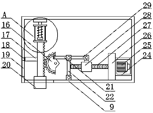
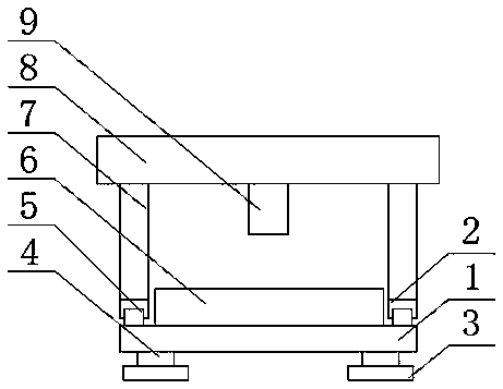
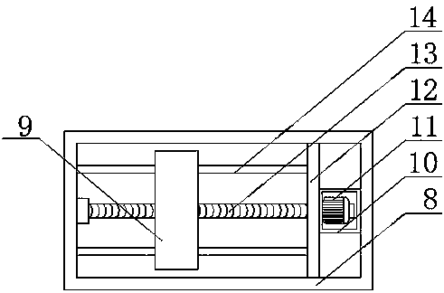
[0018] refer to Figure 1-4 , a lifting device for automation equipment, comprising a bearing plate 1, electric guide rails 5 are provided on both sides of the upper end of the bearing plate 1, and second sliders 2 are installed on the upper ends of the electric guide rails 5, and the upper ends of the second sliders 2 are fixed There are support plates 7, which play the role of support. The upper ends of the two support plates 7 are jointly fixed with a first fixed plate 8. The first fixed plate 8 is provided with a first cavity, and one end of the first cavity is fixed on the side wall. There is a first protection box 10, a first driving device 11 is fixed on the s...


PUM


Abstract

The invention discloses a lifting device of automatic equipment. The lifting device comprises a bearing plate, wherein electric guide rails are respectively arranged at both sides of the upper end ofthe bearing plate; second slide blocks are respectively arranged at the upper ends of the electric guide rails; a support plate is fixedly arranged at the upper end of each second slide block; a firstfixed plate is fixedly arranged at the upper ends of the two support plates; the interior of the first fixed plate is provided with a first cavity; a first protecting box is fixedly arranged at the side wall of one side of the first cavity; a first driving device is fixedly arranged at the side wall of one end of the first protecting box; a second fixed plate is fixedly arranged at one end of thefirst protecting box; both ends of the second fixed plate are respectively fixedly arranged at the side walls of both ends of the first cavity. The lifting device of the automatic equipment has the advantages that the problem of automatic lifting of cutting equipment is solved; by using a spring, the stability is improved; the multi-bearing movement effect is realized, the convenience in use is realized, and the lifting device is suitable for being popularized.

Description

technical field [0001] The invention relates to the technical field of automation equipment, in particular to a lifting device for automation equipment. Background technique [0002] Glass cutting machine refers to a kind of processing machinery specially used for glass processing and blanking. Glass cutting machine includes air-floating sheet feeding table and double-bridge overpass cutting table arranged head to tail. As an improvement, the double bridge interchange type cutting table is between the first straight beam and the second straight beam at the head of the length direction of the upper frame and the third straight beam and the fourth straight beam at the head of the length direction of the lower frame. There is a glass conveying mechanism including a rotating shaft, several conveying wheels, a motor, and a belt; the air-floating film feeding table is equipped with a proximity switch connected to the power control circuit of the motor at the end of the length dire...

Claims


Application Information

Patent Timeline
Patent Type & Authority Applications(China)
IPC IPC(8): C03B33/037
CPCC03B33/037
Inventor 袁红
Owner 常熟梁方智能技术有限公司
Learn More