
Underground pile continuous wall construction method and wall formation device for underground pile continuous wall construction method

A construction method and technology of wall forming equipment, which are applied in sheet pile wall, foundation structure engineering, earth moving machine/shovel excavator, etc. Increase connection solidity, good effect and fast work efficiency

Pending Publication Date: 2018-08-24
连云港市云达建设工程有限公司
View PDF8 Cites 2 Cited by
  • Summary
  • Abstract
  • Description
  • Claims
  • Application Information

AI Technical Summary

Problems solved by technology

[0003] The current construction process of the diaphragm wall is as follows: 1: Excavate a deep groove under the condition of the mud retaining wall, and after forming a unit groove section, place a prefabricated steel cage in the groove, and then pour the concrete with the conduit method to complete the construction of a unit The wall section, the joints between the unit wall sections are connected to each other; 2: The construction of the hydraulic grabbing head machinery and equipment, during the construction process, if there are stones or sundries in the ground or the strength of the rock penetration is high, the construction cannot be carried out; 3: The construction process In the process, the mud on the adjacent walls will affect the bonding between the later walls, because the mud will block the effective bonding between the concrete and the wall
In turn, there will be gaps between the walls in the later stage, water seepage, etc., and the quality standards will not be met. For example, the hydraulic grab equipment is difficult to meet the construction requirements due to poor geological conditions.

Method used


Image

  • Underground pile continuous wall construction method and wall formation device for underground pile continuous wall construction method
  • Underground pile continuous wall construction method and wall formation device for underground pile continuous wall construction method
  • Underground pile continuous wall construction method and wall formation device for underground pile continuous wall construction method

Examples


Embodiment 1

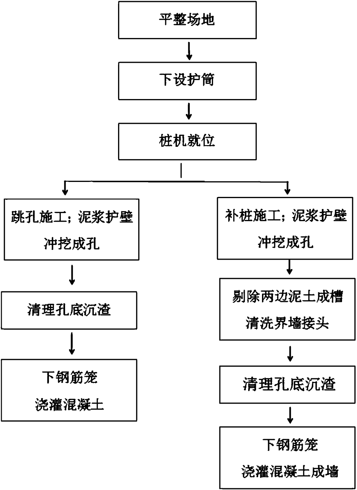
[0066] Through the construction method of underground piles connecting walls, this construction technology is applied to underground piles connecting walls, combined with Figure 2-4 , the steps include the following:

[0067] S1: Leveling the site;

[0068] S2: Underneath the casing;

[0069] S3: the pile driver is in place;

[0070]S4: Start the pile driver to jump the piles in sequence and align them with the pile positions, use the mud retaining head to dig down under the action of the guide rod and the main engine, and use the punching head to grab the soil, debris and stones from the groove and take them out of the ground , carry out step by step according to the above steps, punching and digging the groove to the level of the bottom of the wall, forming a jumping grid unit groove (such as figure 2 shown);

[0071] S5: Clean up the sediment at the bottom of the hole, measure the mud concentration,

[0072] S6: Pour concrete in the lower reinforcement cage to comple...

Embodiment 2

[0078] combined with Figure 5-7 , by the method of the present invention, be used for construction underground pile connecting wall, described steps are as follows:

[0079] S1: Leveling the site;

[0080] S2: Underneath the casing;

[0081] S3: the pile driver is in place;

[0082] S4: Arrange jump hole construction according to the pile position, punch and excavate the mud retaining wall to the set depth,

[0083] S5: Clean up the sediment at the bottom of the hole and measure the mud concentration;

[0084] S6: Concrete is poured with reinforcement cages to complete a jump hole unit wall section;

[0085] S7: Pile filling construction, mud retaining wall punching and digging into holes;

[0086] S8: Eliminate the soil on the two boundary walls to form grooves, the high-pressure nozzle moves up and down along the guide rod, and the water slurry punches to clean the joints of the two boundary walls;

[0087] S9: Clean up the sediment at the bottom of the hole and measu...


PUM


Abstract

The invention discloses an underground pile continuous wall construction method and a wall formation device for the underground pile continuous wall construction method. The underground pile continuous wall construction method is characterized by comprising the steps that S1, land is leveled; S2, a pile casing is arranged underground; S3, a pile driver is placed in position; S4, jump holes are arrayed according to pile positions for construction, and a slurry protection wall is flushed and dug to form a hole with a set depth; S5, sediment at the bottom of the hole is removed, and the slurry condensation is measured; S6, a reinforcement cage is placed downwards, concrete is poured, and thus, one jump-hole unit wall section is completed; S7, pile adding construction is conducted, and the slurry protection wall is flushed and dug to form another hole; S8, mud in two boundary walls is removed, high-pressure spray heads move up and down along guide rods, and thus, joints of the two boundarywalls are flushed, cut and cleaned with water slurry; S9, sediment at the bottom of the hole is removed, and the slurry concentration is measured; and S10, a reinforcement cage is placed downwards, and concrete is poured to form a wall body. By adoption of the construction method, firstly, mud between the joints of the wall bodies is removed, so that the connection firmness between the wall bodies are improved, and the quality problems such as gaps and water seepage between the wall bodies caused by mud between the wall bodies can be effectively solved; secondly, sediment at the bottoms of the holes is mechanically removed, so that the work efficiency is high, sediment is completely removed, the effect is good, and a traditional floating removal method is changed; and thirdly, hole formation based on flushing and digging is practical under complex geological conditions such as a sandy gravel condition and a backfill miscellaneous stone condition, grooves can be formed in rocks, and thus, the construction quality requirement is met.

Description

technical field [0001] The invention belongs to the technical field of engineering construction, and in particular relates to an underground pile connecting wall construction method and wall forming equipment thereof. Background technique [0002] Diaphragm wall, also known as underground diaphragm wall, is a foundation project that uses a trenching machine under the ground to excavate a deep groove along the peripheral axis of the deep excavation project under the condition of mud retaining wall, and hang steel bars in the groove Cage, and then use the conduit method to pour underwater concrete to build a unit wall segment. This is carried out section by section, and a continuous reinforced concrete wall is built underground as a water-stop curtain and a supporting load-bearing structure. [0003] The current construction process of the diaphragm wall is as follows: 1: Excavate a deep groove under the condition of the mud retaining wall, and after forming a unit groove sec...

Claims


Application Information

Patent Timeline
IPC IPC(8): E02D5/38E02D15/04E02F5/20
CPCE02D5/38E02D15/04E02F5/20
Inventor 黄忠仁黄继峰黄继康
Owner 连云港市云达建设工程有限公司
Learn More