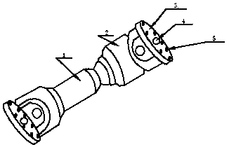
Coupler for car

A coupling and automobile technology, applied in the field of automobile parts, can solve the problems of high manufacturing cost, complicated maintenance, thermal expansion, etc., and achieve the effects of simple and convenient installation, simple maintenance process, and high safety performance.

Inactive Publication Date: 2018-08-24
常州海洛轴承制造有限公司
View PDF0 Cites 1 Cited by
  • Summary
  • Abstract
  • Description
  • Claims
  • Application Information

AI Technical Summary

Problems solved by technology

[0002] The rapid development of modern society has driven the rapid development of automobiles. Couplings are a necessary part of automobiles. Couplings refer to connecting two shafts or shafts and rotating parts, and they rotate together during the process of transmitting motion and power. , a device that does not disengage under normal circumstances, and is sometimes used as a safety device to prevent excessive loads on the connected parts and play the role of overload protection. Most of the commonly used couplings have been standardized or Standardization, in general, it is only necessary to correctly select the type of coupling, and determine the type and size of the coupling. Couplings are generally divided into rigid couplings and flexible couplings. The current couplings Or it can only ensure high alignment between the two shafts, large transmission torque, or a single existence with buffer and shock absorption functions, high manufacturing costs, complicated assembly and disassembly, maintenance, and easy deformation during work Axial offset, radial offset, angular offset, or comprehensive offset caused by thermal expansion, deformation during work, thermal expansion, etc. have a high probability of occurrence

Method used


Image

  • Coupler for car
  • Coupler for car

Examples


Embodiment Construction

[0014] The following will clearly and completely describe the technical solutions in the embodiments of the present invention with reference to the accompanying drawings in the embodiments of the present invention. Obviously, the described embodiments are only some, not all, embodiments of the present invention. Based on the embodiments of the present invention, all other embodiments obtained by persons of ordinary skill in the art without making creative efforts belong to the protection scope of the present invention.

[0015] In the description of the present invention, it should be noted that the terms "center", "upper", "lower", "left", "right", "vertical", "horizontal", "inner", "outer" etc. indicate The orientation or positional relationship is based on the orientation or positional relationship shown in the drawings, and is only for the convenience of describing the present invention and simplifying the description, rather than indicating or implying that the referred de...


PUM


Abstract

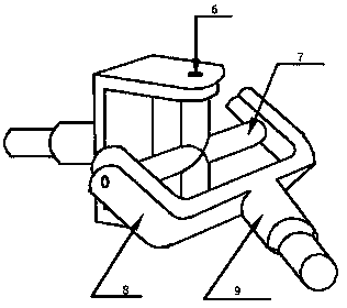
The invention discloses a coupler for a car. The coupler comprises a connecting shaft, conversion parts, connecting pieces, center holes, positioning holes, pins, driven shafts, buckles and driving shafts; the conversion parts are arranged on the left side and the right side of the connecting shaft, the driving shafts are arranged on the outer sides of the conversion parts, the buckles are arranged on the outer sides of the driving shafts, the driven shafts are arranged in the buckles, the pins are arranged at the two ends of each driven shaft, the connecting pieces are arranged on the front ends of the conversion parts, the center holes are formed in the center portions of the connecting pieces, and the positioning holes are formed in the end faces of the connecting pieces. The coupler iseasy and convenient to mount, safety is higher, machining cost is low, the mounting, dismounting and maintaining process is simple and convenient, the coupler can ensure higher centering of two shafts, transmission torque is large, buffering is ensured, vibration is reduced, during work, deforming or thermal expansion is not prone to happening, and therefore the occurrence probability of axial shifting and the like caused by reasons of deforming, or thermal expansion and the like during work is low.

Description

[0001] The invention relates to the technical field of parts for automobiles, in particular to a shaft coupling for automobiles. Background technique [0002] The rapid development of modern society has driven the rapid development of automobiles. Couplings are a necessary part of automobiles. Couplings refer to connecting two shafts or shafts and rotating parts, and they rotate together during the process of transmitting motion and power. , a device that does not disengage under normal circumstances, and is sometimes used as a safety device to prevent excessive loads on the connected parts and play the role of overload protection. Most of the commonly used couplings have been standardized or Standardization, in general, it is only necessary to correctly select the type of coupling, and determine the type and size of the coupling. Couplings are generally divided into rigid couplings and flexible couplings. The current couplings Or it can only ensure high alignment between the ...

Claims


Application Information

Patent Timeline
Patent Type & Authority Applications(China)
IPC IPC(8): F16D3/40
CPCF16D3/40
Inventor 吴亚新
Owner 常州海洛轴承制造有限公司
Why Eureka
Try Eureka