Valve lock and valve management and control system

A technology of valves and locks, which is applied in the direction of valve details, valve devices, engine components, etc., can solve the problems of valve control, damage, and valve status that cannot be unlocked, and achieve the effect of structural stability

Active Publication Date: 2018-08-24
CYG CONTRON
View PDF5 Cites 3 Cited by
  • Summary
  • Abstract
  • Description
  • Claims
  • Application Information

AI Technical Summary

Problems solved by technology

[0004] In the prior art, in order to prevent the valve from being mishandled, a locking device is provided on the valve. However, the locking device in the prior art only covers and seals the hand wheel, and the locking device is easily shaken and damaged.
In addition, the existing locking device can only lock the valve but cannot control the unlocked valve, let alone detect the status of the valve, which is not conducive to systematic management and monitoring

Method used


Image

  • Valve lock and valve management and control system
  • Valve lock and valve management and control system
  • Valve lock and valve management and control system

Examples


Embodiment 1

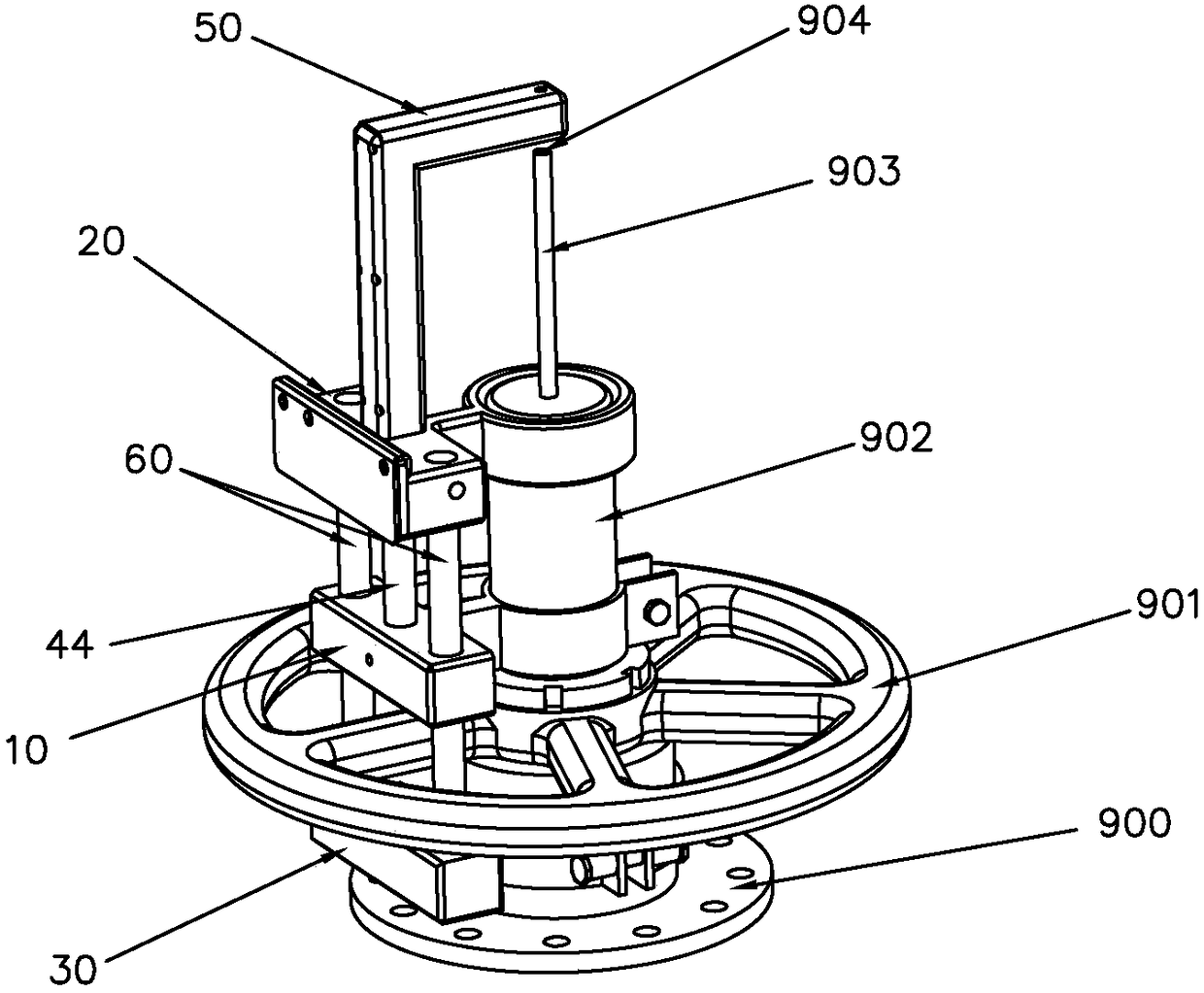
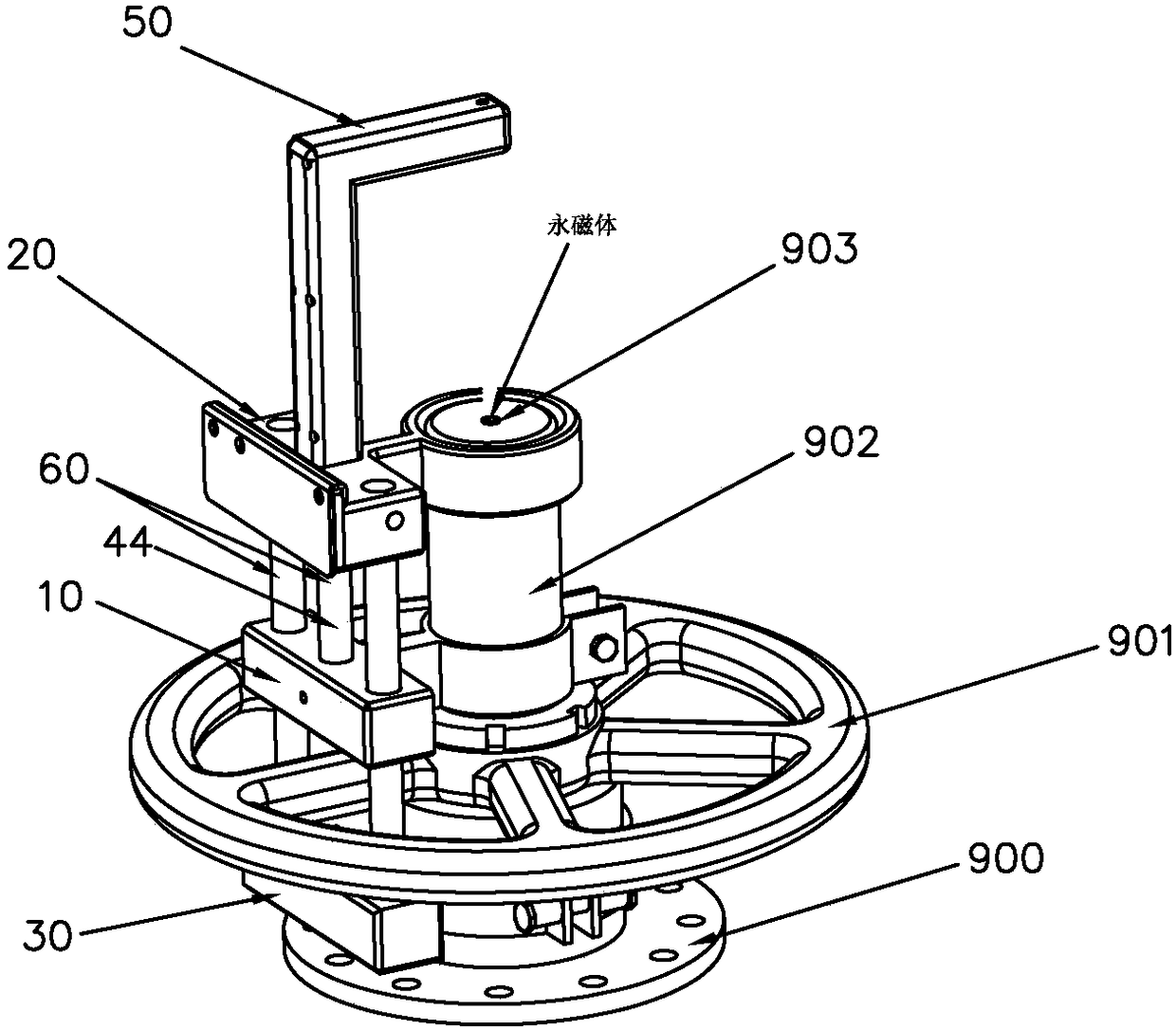
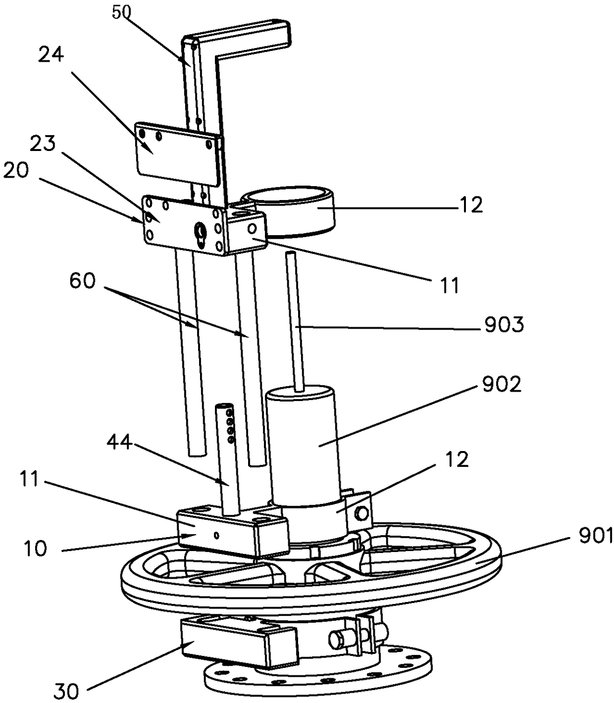
[0041] This embodiment provides a valve lock, which is used to control the valve so that the valve cannot be manipulated at will. figure 1 , figure 2 and image 3A schematic diagram of the cooperation between the valve lock and the relevant parts of the valve is given, wherein the controlled valve includes a valve body 900 (the part of the valve body is shown in the figure), a hand wheel 901, a hand wheel pressure piece 902 and a valve stem 903, and the valve body 900 There are two ports and a fluid channel connecting the two ports. The valve stem 903 is assembled on the valve body 900, the lower part is used to control the opening and closing of the fluid channel, and the upper part extends out of the valve body; It is rotatably assembled at the position of the extension part of the valve stem, and is used to limit the axial movement of the handwheel relative to the valve body; the handwheel 901 controls the valve stem 903 to rise or fall in the center hole of the handwheel...

Embodiment 2

[0056] Embodiment 2 provides a valve control system on the basis of the valve lock provided in Embodiment 1, combining Figure 14 As shown, the valve management and control system includes a parameter acquisition device, a management host, a mobile terminal, a computer key and a lock; the acquisition end of the parameter acquisition device is set at the parameter acquisition position involved in the process flow of the valve, and the parameter output end is connected to the management The parameter input terminal of the main engine; the communication connection between the management host and the mobile terminal, and the communication connection between the mobile terminal and the computer key; the computer key supplies power to the lock, communicates with the lock, and cooperates with the mechanical unlocking of the lock; the lock adopts the valve lock described in Embodiment 1 .

[0057] The working principle of the above valve control system is explained as follows:

[005...


PUM


Abstract

The invention discloses a valve lock and a valve management and control system, and provides a lock for locking and managing and controlling a valve. The lock is characterized in that a fixed lock body is fixedly arranged on a handwheel pressing part of the valve, wherein a movable lock body is locked to or released from the fixed lock body through a fixing mechanism, so that a handwheel interference mechanism which is arranged on the movable lock body is capable of limiting the rotating of a handwheel. The valve lock has the characteristics of being stable in structure, practicable and reliable. Additionally, the valve state can be detected in a manner of arranging an electromagnetic element on a valve rod, arranging a valve state detector on the movable lock body and arranging a state detecting circuit in the lock. The valve lock can be matched with a computer key, a parameter acquiring device and a management host computer to form a complete set of valve management and control system which realizes systemic management and monitoring on the valve unlocking and locking control and on-off state detecting.

Description

technical field [0001] The invention relates to a valve lock and a valve control system based on the lock. Background technique [0002] Valves are used for flow control and have a wide range of applications. Taking the petrochemical industry as an example, a large number of valves are used in its transportation system, measurement and control system, etc. According to different application requirements or environments, there are various valves. There are certain differences in the structure or size of these valves, but the basic principles are similar. [0003] Flat plate valve is a kind of valve commonly used in the field of petrochemical industry, mainly used in oil and gas pipelines. The flat plate valve includes valve body, valve stem, handwheel and handwheel pressure piece. When the handwheel is turned to open the valve, the valve stem will rise upwards, and when it rises to the highest point, the valve will be fully opened; Descending, when reaching the lowest poin...

Claims


Application Information

Patent Timeline
Patent Type & Authority Applications(China)
IPC IPC(8): F16K35/00F16K37/00
CPCF16K35/00F16K37/0041
Inventor 王振贤谢小渭魏略夏锐黄建林李艳
Owner CYG CONTRON
Why Eureka
Try Eureka