Bridge amplitude real-time monitor

A technology for real-time monitors and bridges, applied to instruments, measuring devices, elastic testing, etc., can solve the problems of long data sampling delay, inability to achieve zero-state frequency response, and long cycle of page change in the tube, and improve the detection range , Improving the accuracy of disturbance measurement and improving the effect of recognition accuracy

Pending Publication Date: 2018-08-24
李自强 +2
View PDF7 Cites 3 Cited by
  • Summary
  • Abstract
  • Description
  • Claims
  • Application Information

AI Technical Summary

Problems solved by technology

The disadvantages are: the page change cycle in the tube is long, so that the data sampling delay is long, and the real-time structural dynamic effect under various loads cannot be drawn in time, and the zero-state frequency response cannot be achieved
Output positioning results at a rate of 10-20hz, and the measurement parameters are difficult to meet the requirements of real-time health monitoring

Method used


Image

  • Bridge amplitude real-time monitor
  • Bridge amplitude real-time monitor
  • Bridge amplitude real-time monitor

Examples


Embodiment 1

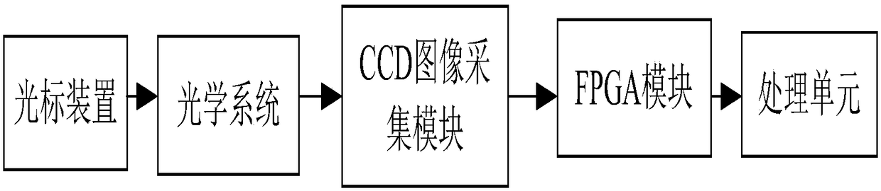
[0030] Such as figure 1 A bridge amplitude real-time monitor is shown, including a cursor device, an optical system, a CCD image acquisition module, an FPGA module and a processing unit; the cursor device forms a light spot and is installed on the bridge amplitude point, and the optical system images the cursor device on the CCD The image acquisition module receives the area array so that the CCD image acquisition module can receive the image information of the cursor device at a long distance. The FPGA module judges the bridge amplitude according to the center movement of the cursor device in the cursor device image before and after the bridge vibration, and the processing unit performs data processing on the output information of the FPGA module. Process, control each module and control the communication between each module.

[0031]When installing the cursor device, it is preferred to install it at the amplitude-sensitive point of the bridge. The optical system is aligned w...

Embodiment 2

[0033] Based on the principles of the above-mentioned embodiments, this embodiment refines its specific implementation, that is, the cursor device includes a light outlet, an LED light arranged at the light outlet, a driving circuit for driving the LED light, and a device for controlling the working state of the LED light. Photoelectric switch. The light of the LED lamp is emitted through the light outlet, and a beam shaper is installed on the light outlet. The shape of the light exit can be a circle, a square or a regular triangle, or an ellipse, a regular five-pointed star, an isosceles trapezoid, etc., preferably a circle, which reduces the amount of data calculated by the amplitude value of the image recognition feature in the later stage, and can Simplifies the difficulty of subsequent center identification. The circular feature is formed at the back of the circular light outlet, and the coordinates of the center point of the cursor are analyzed through image binarizatio...


PUM


Abstract

The invention discloses a bridge amplitude real-time monitor, comprising a cursor device added to an amplitude point of a bridge, an optical system for imaging the cursor device on a receiving area array of a CCD (Charge Coupled Device) image acquisition module, an FPGA (Field Programmable Gate Array) module for judging the bridge amplitude according to the center movement condition of the cursordevice in an cursor device image before and after the vibration of the bridge, and a processing unit for performing data processing on the output information of the FPGA module and controlling the communication between various modules. The bridge amplitude real-time monitor is based on an image recognition technology; since the optical system is added in front of the receiving area array of the CCD image acquisition module, the image is clearly imaged, the detection range is greatly improved, the recognition accuracy of cursor center can be improved, and the immunity measurement accuracy is improved.

Description

technical field [0001] The invention relates to the field of bridge detection devices, in particular to a bridge amplitude real-time monitor. Background technique [0002] The deflection and deformation of the bridge is an important parameter for the evaluation of the health status of the bridge. It is necessary to accurately measure the static and dynamic deflection values ​​of the bridge in the aspects of bridge inspection, renovation of dangerous bridges, and acceptance of new bridges. With the advancement of bridge health monitoring technology, many methods for displacement and deflection measurement have been studied. At present, there are many methods for measuring bridge deflection at home and abroad. The principles, characteristics and scope of application of several common measurement methods are briefly introduced below. [0003] Traditional manual measurement methods: [0004] (1) Dial indicator measurement method. The dial gauge measurement method is a more tr...

Claims


Application Information

Patent Timeline
Patent Type & Authority Applications(China)
IPC IPC(8): G01M5/00
CPCG01M5/0008G01M5/005
Inventor 李自强叶修辰滕华
Owner 李自强
Why Eureka
Try Eureka