
A Calibration Method of Hierarchical TDC Using Delay Chain Structure

A correction method and delay chain technology, applied in the field of time-to-digital conversion, can solve problems such as uncertain position relationship of rising edge of external input signal, DFF error output code, etc.

Active Publication Date: 2020-04-07
山东天聚汇能微电子有限公司
View PDF5 Cites 0 Cited by
  • Summary
  • Abstract
  • Description
  • Claims
  • Application Information

AI Technical Summary

Problems solved by technology

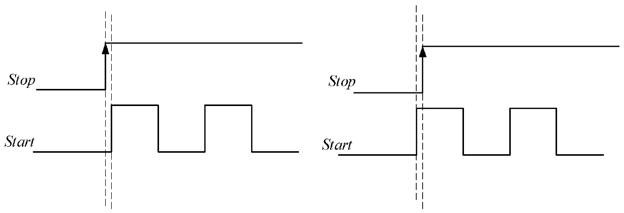
[0005] The present invention is to solve the problem that in the digital delay chain TDC, the positional relationship of the rising edge of the external input signal is uncertain, which will lead to the problem that the DFF will have the wrong output code, and now provides a correction method of the hierarchical TDC adopting the delay chain structure

Method used


Image

  • A Calibration Method of Hierarchical TDC Using Delay Chain Structure
  • A Calibration Method of Hierarchical TDC Using Delay Chain Structure
  • A Calibration Method of Hierarchical TDC Using Delay Chain Structure

Examples


specific Embodiment approach 1

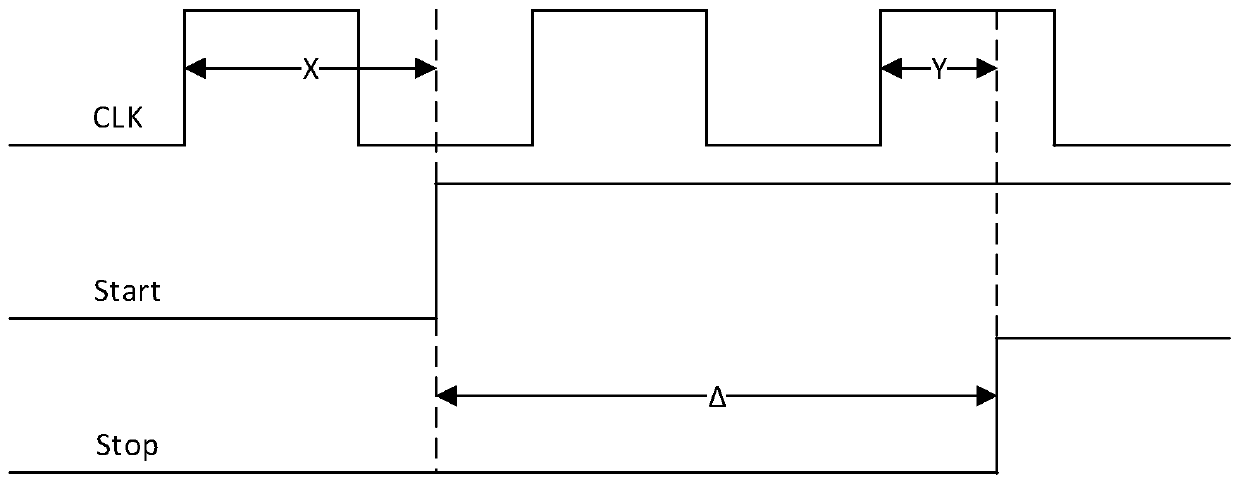
[0027] Specific implementation mode one: refer to figure 1 Specifically describe this embodiment, a correction method for a hierarchical TDC using a delay chain structure described in this embodiment,

[0028] When the start signal Start arrives, the reference clock counter counts the reference clock CLK, and at the same time, the start signal Start is sent to the delay chain, and the time interval X between the start signal Start and the reference clock CLK is obtained, 0≤X≤T, where T represents The time of one cycle of the reference clock CLK,

[0029] When the stop signal Stop arrives, the reference clock counter stops counting and obtains the number of reference clock cycles N between the start signal Start and the stop signal Stop. At the same time, the stop signal Stop is sent into the delay chain, and the stop signal Stop and the reference clock CLK are obtained. The time interval Y, 0≤Y≤T.

[0030] Correct the reference clock cycle number N,

[0031] Suppose the in...


PUM


Abstract

A correction method for a hierarchical TDC adopting a delay chain structure relates to the technical field of time-to-digital conversion. The invention aims to solve the problem that in the digital delay chain TDC, the rising edge position relationship of the external input signal is uncertain, which further leads to the problem that the DFF will produce wrong output codes. A correction method for a hierarchical TDC adopting a delay chain structure according to the present invention, by comparing the relative position between the edge of the DFF sampling signal and the edge of the sampled signal, and the time interval between the two signals measured by the delay chain To correct the TDC measurement error caused by not meeting the DFF setup time and hold time.

Description

technical field [0001] The invention belongs to the technical field of time-to-digital conversion, in particular to a correction method for a time-to-digital converter (TDC) with hierarchical structure. Background technique [0002] TDC is a circuit that is widely used at present. Its function is to convert the time interval between two signals into a digital quantity. Its general working principle is based on the delay chain. figure 2 It is a typical digital delay chain TDC basic structure diagram, which is composed of a delay chain composed of N delay units (buffer) connected in series and a flip-flop (DFF) for sampling the output of each delay unit. Assuming that the delay time of each buffer to the input signal is t, according to figure 1 It can be seen from the signal waveforms of Start and Stop in the middle that the output digital code Q of the TDC N-1 ...Q 2 Q 1 Q 0 The form is 0...01...1. If the number of low bit output "1" is N, the time interval between the...

Claims


Application Information

Patent Timeline
Patent Type & Authority Patents(China)
IPC IPC(8): G04F10/00
CPCG04F10/005
Inventor 罗敏王晨旭刘晓宁王新胜
Owner 山东天聚汇能微电子有限公司
Learn More