Steam generator primary-side structure capable of alleviating backflow of U-shaped pipes

A steam generator and U-tube technology, which is applied in nuclear power generation, climate sustainability, reactors, etc., can solve the problems of local backflow, differences in fluid dynamic characteristics, etc., and achieve the effect of improving performance.

Active Publication Date: 2018-08-24
NUCLEAR POWER INSTITUTE OF CHINA
View PDF4 Cites 2 Cited by
  • Summary
  • Abstract
  • Description
  • Claims
  • Application Information

AI Technical Summary

Problems solved by technology

[0004] The purpose of the present invention is to provide a steam generator primary side structure that can alleviate U-shaped tube backflow, and solve the local b

Method used


Image

  • Steam generator primary-side structure capable of alleviating backflow of U-shaped pipes
  • Steam generator primary-side structure capable of alleviating backflow of U-shaped pipes
  • Steam generator primary-side structure capable of alleviating backflow of U-shaped pipes

Examples


Embodiment 1

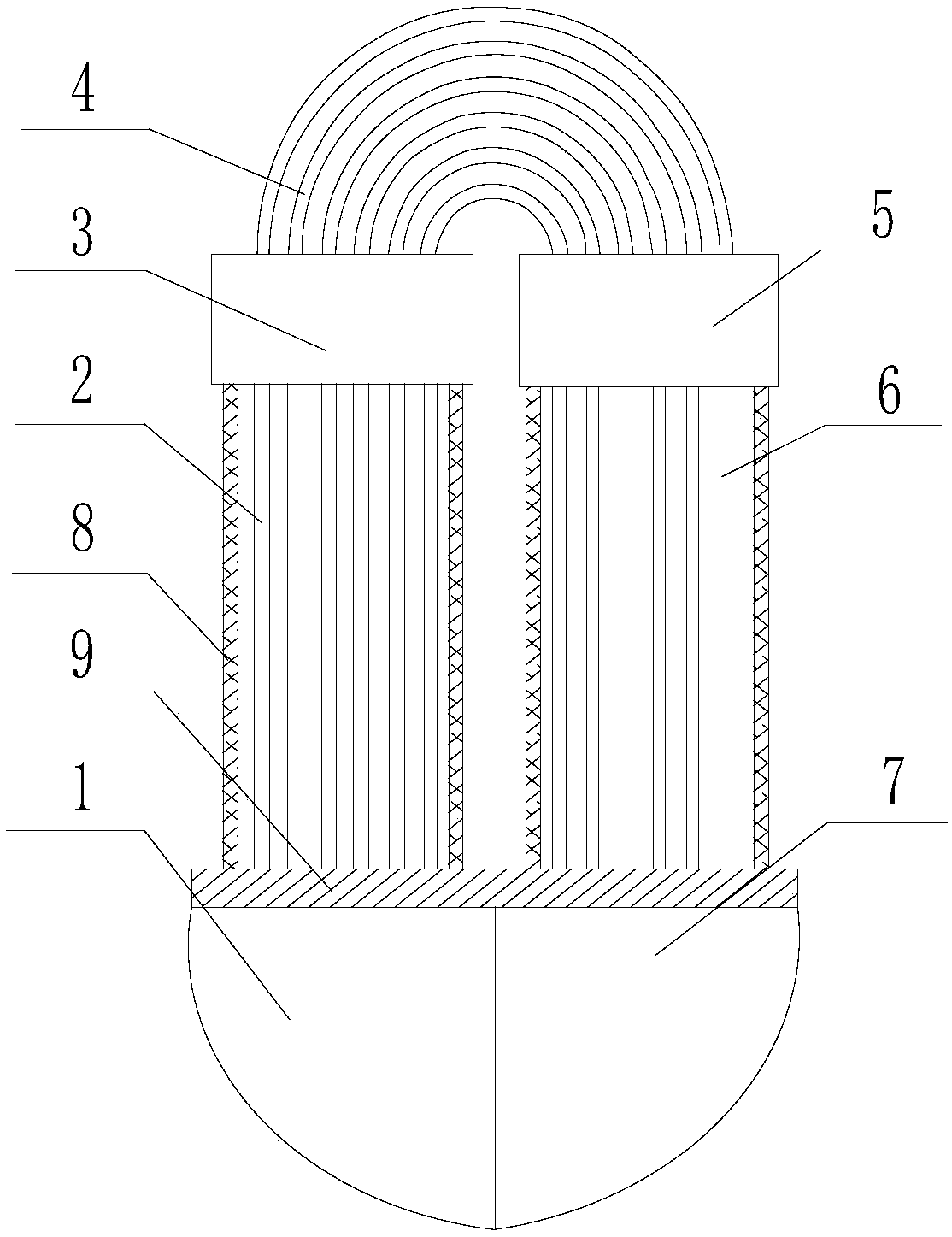
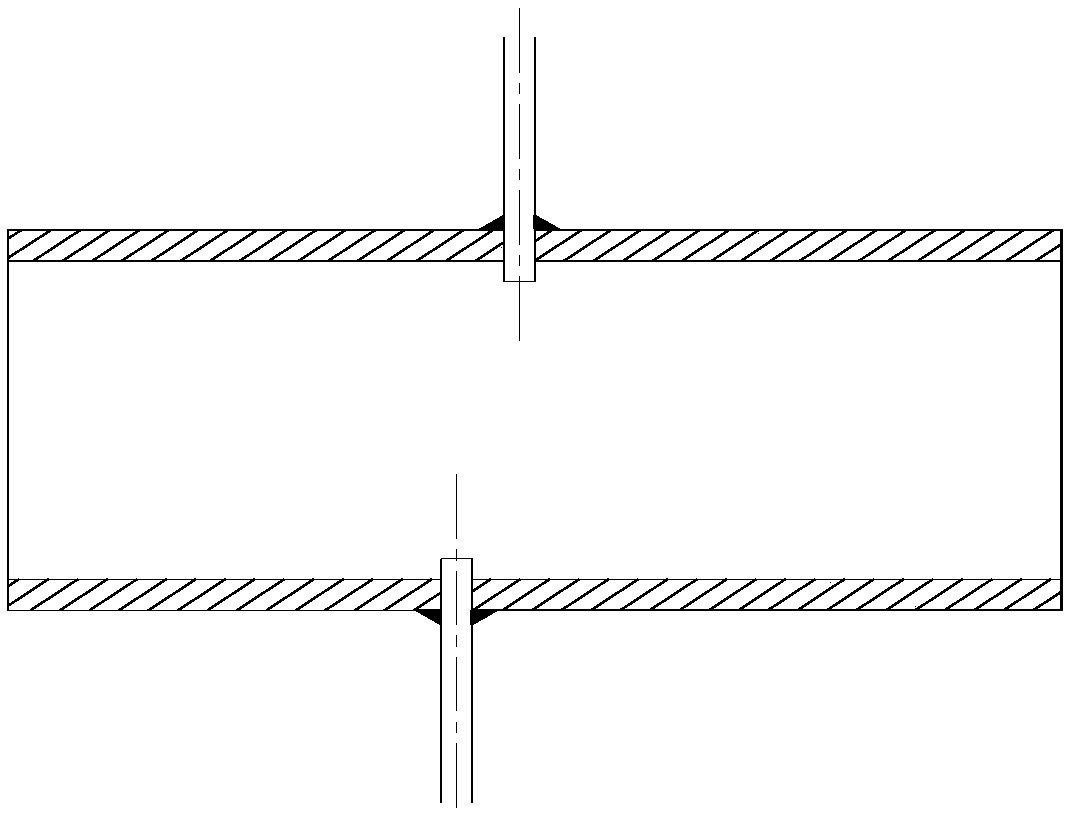
[0032] Such as Figure 1 to Figure 3 As shown, a steam generator primary side structure that can relieve U-shaped tube backflow includes several U-shaped tubes arranged in parallel, and the U-shaped tube includes an inlet straight pipe section 2, a curved section 4 and an outlet straight pipe section 6. The inlet end and the outlet end of the curved section 4 are respectively connected to the outlet end of the inlet straight pipe section 2 and the inlet end of the outlet straight pipe section 6, and the outlet end of the inlet straight pipe section 2 and the inlet end of the curved section 4 pass through the inlet intermediate header 3 connection, the inlet end of the outlet straight pipe section 6 is connected to the outlet end of the curved section 4 through the outlet intermediate header 5, specifically, the outlet end of the inlet straight pipe section 2 is inserted into the lower part of the inlet intermediate header 3, and the curved The inlet end of section 4 is inserte...

Embodiment 2

[0041] Such as Figure 1 to Figure 3 As shown, this embodiment is based on Embodiment 1. Two support columns 8 are arranged between the tube sheet 9 and the inlet intermediate header 3, and two support columns are arranged between the tube sheet 9 and the outlet intermediate header 5. Column 8.

[0042] In this embodiment, the bottom of the support column 8 is welded to the upper end surface of the tube plate 9 , and the top of the support column 8 is welded to the bottom of the inlet intermediate header 3 and the bottom of the outlet intermediate header 5 . By setting the support column 8, the installation stability of the inlet intermediate header 3 and the outlet intermediate header 5 is improved.

Embodiment 3

[0044] Such as Figure 1 to Figure 3 As shown, this embodiment is based on embodiment 1, the length of the outlet end of the inlet straight pipe section 2 and the inlet end of the curved section 4 inserted into the inlet intermediate header 3 is 2-3cm; the inlet end of the outlet straight pipe section 6 , The length of the outlet end of the curved section 4 inserted into the outlet middle header 5 is 2-3cm.

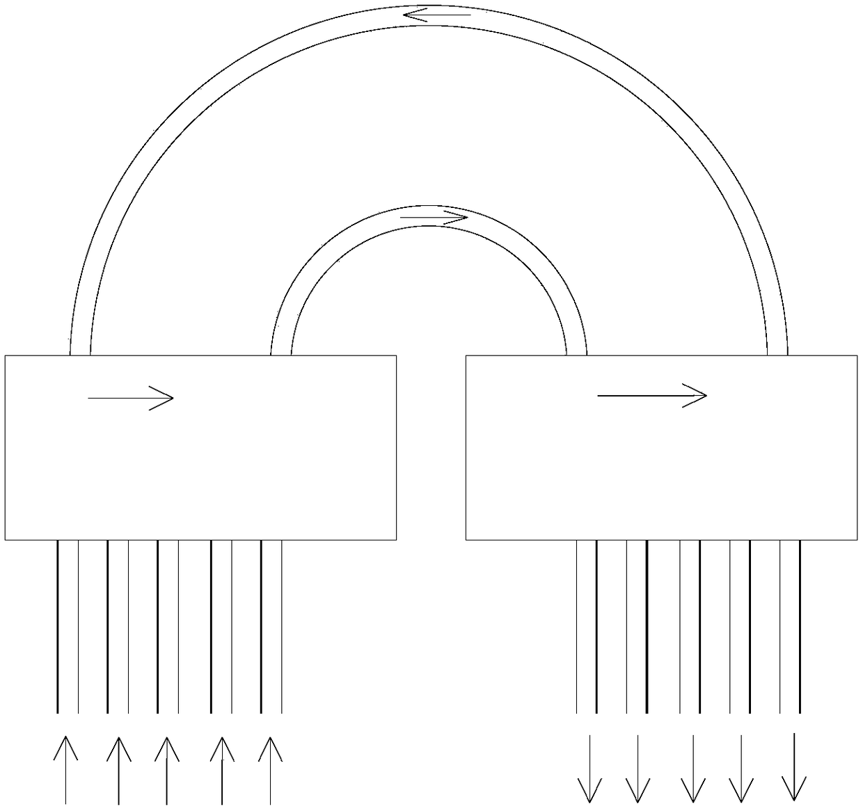
[0045] In this embodiment, the lengths of the inlet intermediate header 3 and the outlet intermediate header 5 are set to 2-3 cm by inserting the inlet straight pipe section 2 , the curved section 4 and the outlet straight pipe section 6 . The mixing effect of the airflow in the inlet intermediate header 3 and the outlet intermediate header 5 can be improved.


PUM


Abstract

The invention discloses a steam generator primary-side structure capable of alleviating backflow of U-shaped pipes. The steam generator primary-side structure comprises several parallel-connection U-shaped pipes, the parallel-connection U-shaped pipes comprise an inlet straight-tube segment, a bending segment and an outlet straight-tube segment, an inlet end and an outlet end of the bending segment are respectively connected with the outlet end of the inlet straight-tube segment and the outlet end of the outlet straight-tube segment, the outlet end of the inlet straight-tube segment is connected with the inlet end of the bending segment through an inlet middle header, and the inlet end of the outlet straight tube segment and the outlet end of the bending segment through an outlet middle header. Through the communication effect of the inlet middle header and the outlet middle header, the local backflow phenomenon of the straight-tube segment of the U-shaped pipes can be effectively eliminated, and the backflow of the bending segment of the U-shaped pipes can be alleviated, problems of increased flow resistance and small natural cycle driving force due to backflow can be solved, andthe usage performance of the steam generator under natural cycle condition can be obviously increased.

Description

technical field [0001] The invention relates to the technical field of thermal hydraulics and safety of reactors, in particular to a primary side structure of a steam generator capable of alleviating backflow of U-shaped tubes. Background technique [0002] Saturated steam generators are widely used in pressurized water reactor nuclear power plants. They are the hub connecting the first and second circuits of the reactor for heat transfer, and are the key components of the reactor nuclear island. A number of studies have shown that under the condition of passive waste heat removal using natural circulation, part of the U-shaped tube on the primary side of the saturated steam generator will flow back, and the backflow phenomenon will continue to intensify as the core waste heat decreases. Since the reverse flow will increase the positive flow velocity, increase the flow resistance of the primary side of the steam generator, and cause the mixing of hot and cold fluids, which w...

Claims


Application Information

Patent Timeline
IPC IPC(8): G21C13/02G21C13/032
CPCG21C13/02G21C13/032Y02E30/30
Inventor 唐瑜徐建军周慧辉黄彦平
Owner NUCLEAR POWER INSTITUTE OF CHINA
Why Eureka
Try Eureka