Transformer fly wire winding device

A technology of winding device and transformer, applied in the field of transformer manufacturing

Pending Publication Date: 2018-08-24
贵州金林电子科技有限公司
View PDF1 Cites 0 Cited by
  • Summary
  • Abstract
  • Description
  • Claims
  • Application Information

AI Technical Summary

Problems solved by technology

[0005] The present invention intends to provide a winding device for transformer flying wires, so as to solve the p

Method used


Image

  • Transformer fly wire winding device

Examples


Embodiment Construction

[0014] Further detailed explanation through specific implementation mode below:

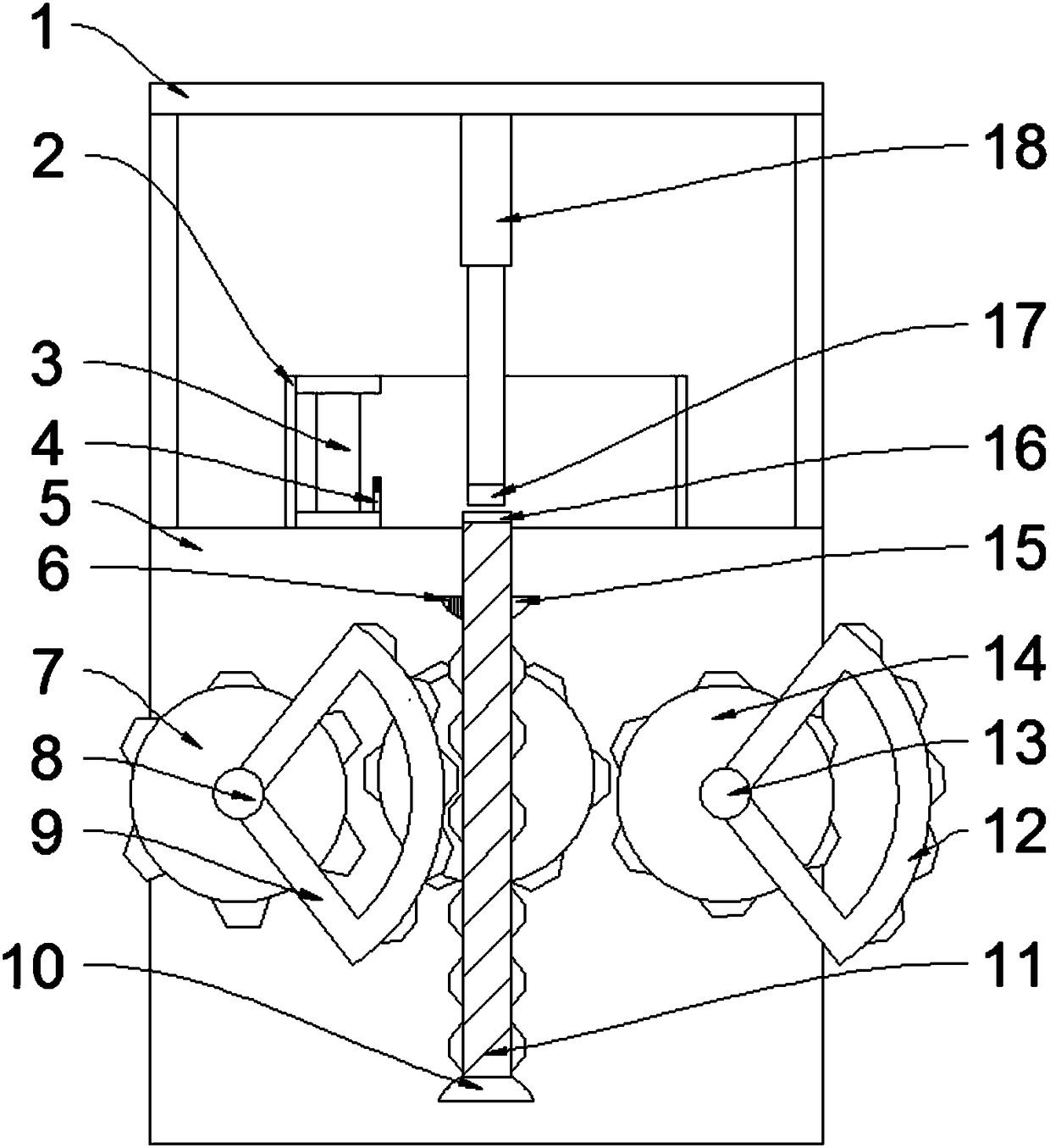
[0015] The reference signs in the accompanying drawings of the description include: fixed frame 1, annular pipe 2, winding reel 3, limit plate 4, fixed plate 5, positioning groove 6, driven wheel 7, driven shaft 8, driven sector wheel 9 , limit ring 10, slide bar 11, driving sector wheel 12, driving shaft 13, driving wheel 14, dividing plate 15, groove 16, extruding block 17, telescoping rod 18.

[0016] The embodiment is basically as attached figure 1 Shown: a winding device for transformer flying wires, including a winding device and a lifting device; the lifting device includes a fixed plate 5, a driving mechanism, a transmission mechanism, a driven mechanism and a slide bar 11 made of magnets; the driven mechanism includes The driven shaft 8, the driven wheel 7 and the driven sector wheel 9 are fixedly connected to the driven shaft 8; An end away from the fixed plate 5, the driving wheel is...


PUM


Abstract

The invention discloses a transformer fly wire winding device in the technical field of transformers. The transformer fly wire winding device comprises a wire winding device body, a sliding rod, a fixed plate, a driving shaft, a driving wheel, a driving sector wheel, a transmission wheel, a transmission shaft, a location rod, a driven shaft, a driven wheel and a driven sector wheel, wherein the driven shaft and the driving shaft are arranged on the fixed plate, the transmission shaft is arranged on the fixed plate, the driving wheel and the transmission wheel are meshed with each other, the transmission wheel and the driven wheel are meshed with each other, a sliding groove is arranged on the sliding rod, a partition plate is arranged on the sliding rod, the sliding rod is divided into a smooth part and a meshed part by the partition plate, and the two sides of the meshed part are respectively meshed with the driving wheel and the driven wheel; the winding device body comprises an annular pipe, a wire winding rod and two stopping plates; the stopping plates are meshed with an inner wall of the annular pipe, and a first motor is connected to the wire winding rod; a fixed frame is arranged on the fixed plate, a telescopic rod is arranged on the fixed frame, an extruding block is arranged on the telescopic rod, and the driving shaft is connected with a second motor. A machine is utilized to replace the hand, the hand is prevented from contacting the rotating shaft, and operation can be safer.

Description

technical field [0001] The invention relates to the technical field of transformer manufacturing, in particular to a winding device for transformer flying leads. Background technique [0002] Transformer winding machine is a special equipment for winding transformer coils. During the production process of transformer coils, the winding equipment is divided according to the voltage level or capacity of the transformer. There are automatic wire winding machines for winding high and low voltage coils of distribution transformers. Wire machines and foil coil winding machines; there are vertical winding machines and horizontal winding machines for winding large power transformer coils. [0003] Generally, a small transformer includes an inner frame, a coil and an iron core, the coil is wound on the inner frame, the inner frame includes a central hole, and the iron core is installed in the central hole. The production process of the small transformer is to first insert the inner ...

Claims


Application Information

Patent Timeline
IPC IPC(8): H01F41/082
CPCH01F41/082
Inventor 佘加旭
Owner 贵州金林电子科技有限公司
Why Eureka
Try Eureka