Grounding device for flexible DC power transmission system

A technology for grounding devices and power transmission systems, applied in emergency protection circuit devices, electrical components, power transmission AC networks, etc., can solve problems such as overvoltage and DC bias voltage

Active Publication Date: 2018-08-24
GLOBAL ENERGY INTERCONNECTION RES INST CO LTD +2
View PDF4 Cites 0 Cited by
  • Summary
  • Abstract
  • Description
  • Claims
  • Application Information

AI Technical Summary

Problems solved by technology

However, when a fault occurs inside the converter station, since the zero-sequence current needs to pass through the large resistance connected to the neutral point on the valve side of the transformer, it may cause significant DC bias voltage and overvoltage

Method used


Image

  • Grounding device for flexible DC power transmission system
  • Grounding device for flexible DC power transmission system
  • Grounding device for flexible DC power transmission system

Examples


Embodiment 1

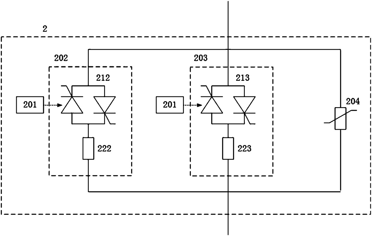
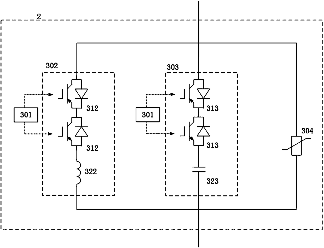
[0051] In this embodiment, the energy absorbing branch includes a non-linear resistor, such as figure 2 and 3 As shown, the energy absorbing branches 204 and 304 may include a non-linear resistor, the voltage across the non-linear resistor and the current flowing through the non-linear resistor have a monotonically increasing relationship, ie have a monotonically increasing voltage-current relationship. In this embodiment, the non-linear resistance of the energy absorbing branch adopts zinc oxide resistance.

[0052] In this embodiment, in order to ensure that the non-linear resistor heating breakdown will not occur under the action of the maximum possible DC voltage and power frequency voltage during the operation of the grounding device, it is necessary to set the grounding device based on the above possible maximum DC voltage and power frequency voltage. Determine the reference voltage of the non-linear resistor.

Embodiment 2

[0054] In this embodiment, the energy absorption branch includes a metal oxide arrester, such as figure 2 and 3 As shown, energy absorbing branches 204 and 304 may include a metal oxide arrester. In this embodiment, the energy absorption capacity of the metal oxide arrester can be set according to the possible maximum DC voltage and power frequency voltage. For example, when the reference current of the metal oxide arrester is 1mA, its energy absorption capacity can be set not less than 10MJ, and when the reference current of the metal oxide arrester is 5mA, its energy absorption capacity can be set not less than 12MJ.

[0055] Further, the control module in this embodiment may include the following structures, specifically:

[0056] In this embodiment, the control module 101 includes a voltage measurement unit, a first trigger unit and a second trigger unit.

[0057] Among them: a voltage measuring unit, used to measure the zero-sequence voltage of the grounding device 2 ...


PUM


Abstract

The invention provides a grounding device for a flexible DC power transmission system, and the grounding device includes a high impedance branch circuit, a low impedance branch circuit and an energy absorption branch circuit, wherein the high impedance branch circuit, the low impedance branch circuit and the energy absorption branch circuit are connected in parallel. The high impedance branch circuit includes a first power electronic switch and a first impedance unit, and the low impedance branch circuit includes a second power electronic switch and a second impedance unit. The grounding device also includes a control module for triggering the first power electronic switch or the second power electronic switch to be turned on so as to connect the first impedance unit or the second impedance unit to the flexible DC power transmission system. Compared with the prior art, the grounding device can connect different impedance branch circuits according to the demands of the actual working conditions of the flexible DC power transmission system. Meanwhile, each of the high impedance branch circuit and the low impedance branch circuit comprises one power electronic switch, so the groundingdevice can flexibly control the switching of the high impedance branch circuit and the low impedance branch circuit.

Description

technical field [0001] The invention relates to the field of power electronics technology, in particular to a grounding device for a flexible direct current transmission system. Background technique [0002] The flexible DC transmission system uses power electronic devices that can be turned off, and by controlling the amplitude and phase angle of the output voltage of the power electronic devices, it can realize fast and independent control of active power and reactive power. The flexibility of operation has significant application advantages in the fields of new energy power generation grid integration, offshore wind power grid integration, large-scale urban power supply, grid interconnection, long-distance high-voltage large-capacity DC transmission, etc. [0003] The traditional HVDC flexible transmission system mainly adopts the high-resistance grounding method of the neutral point of the AC side connected to the valve side of the transformer, which can suppress the imp...

Claims


Application Information

Patent Timeline
Patent Type & Authority Applications(China)
IPC IPC(8): H02J3/36H02H7/26
CPCH02H7/26H02J3/36Y02E60/60
Inventor 李泓志周杨阳岳希别晓玉杜镇宇孙宝宝高凯韩子娇
Owner GLOBAL ENERGY INTERCONNECTION RES INST CO LTD
Why Eureka
Try Eureka