Electromagnetic drive for needle-free injection
An electromagnetic drive, needle-free injection technology, applied in the medical field, can solve the problems of low limit reliability, large output, small output, etc., to achieve the effect of improving the magnetic driving force, enhancing the magnetic field, and overcoming the low reliability
- Summary
- Abstract
- Description
- Claims
- Application Information
AI Technical Summary
Problems solved by technology
Method used
Image
Examples
Embodiment 1
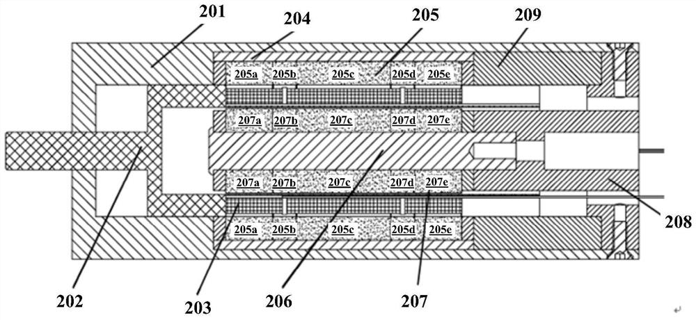
[0047] figure 2 A schematic structural diagram of the electromagnetic drive device according to Embodiment 1 of the present invention is shown. The electromagnetic drive device includes a sheath 201 , a frame 202 , an outer circular iron core 204 , an outer magnet assembly 205 , an inner circular iron core 206 , an inner magnet assembly 207 , an end cover 208 and a spacer 209 .
[0048] The sheath 201 is cylindrical and includes a top opening and a bottom opening. The skeleton 202 is configured to be movably connected to the sheath 201, the skeleton 202 includes a transmission rod extending out of the top opening and adapted to connect to an injection vessel, and a bobbin on which a coil 203 is wound. The outer circular iron core 204 is arranged on the radially inner wall of the middle part of the sheath 201 . The outer magnet assembly 205 is disposed on the radially inner wall of the outer circular iron core 204 . The inner circular iron core 206 is disposed inside the sh...
Embodiment 2
[0059] Figure 5 A schematic structural diagram of an electromagnetic drive device according to Embodiment 2 of the present invention is shown. The electromagnetic drive device includes a sheath 501 , a skeleton 502 , an outer circular iron core 504 , an outer magnet assembly 505 , an inner circular iron core 506 , an inner magnet assembly 507 , an end cover 508 and a spacer 509 . The structural arrangement of the components of the electromagnetic drive device in Embodiment 2 is substantially the same as that of the electromagnetic drive device in Embodiment 1, except for the structure of the outer magnet assembly 505 and the inner magnet assembly 507 . The different parts of this implementation will be described in detail below, and the same or similar parts will not be repeated.
[0060] refer to Figure 5 and 6 , in this implementation, the outer magnet assembly 505 includes seven outer permanent magnet rings 505a, 505b, 505c, 505d, 505e, 505f, 505g. The first outer per...
PUM
 Abstract
Description
Claims
Application Information
 - R&D
- Intellectual Property
- Life Sciences
- Materials
- Tech Scout
- Unparalleled Data Quality
- Higher Quality Content
- 60% Fewer Hallucinations
Browse by: Latest US Patents, China's latest patents, Technical Efficacy Thesaurus, Application Domain, Technology Topic, Popular Technical Reports.
© 2025 PatSnap. All rights reserved.Legal|Privacy policy|Modern Slavery Act Transparency Statement|Sitemap|About US| Contact US: help@patsnap.com


