Supercharge Your Innovation With Domain-Expert AI Agents!

An exhaust gas treatment device

An exhaust gas treatment device and a draft-type technology, which are used in combination devices, separation methods, dispersed particle separation, etc., can solve the problems of long treatment time, harm to the environment, imperfect design, etc., and achieve high exhaust gas treatment efficiency, simple installation and fixation, The effect of compact structure design

Active Publication Date: 2021-01-29
TANGSHAN LUAN SHUO INORGANIC SILICIDE LTD
View PDF6 Cites 0 Cited by
  • Summary
  • Abstract
  • Description
  • Claims
  • Application Information

AI Technical Summary

Problems solved by technology

[0002] In addition to the production of products, industrial production is also accompanied by the generation of waste gas and waste. Waste is easier to collect and utilize, but waste gas collection is difficult and harmful to the environment. People pay more and more attention to the treatment of waste gas. However, the currently used waste gas treatment devices, The design is not perfect, and the collection is not perfect, and there are various problems in actual use
[0003] In order to solve the above problems, the present invention is proposed, which overcomes the problems of insufficient waste gas treatment and long processing time due to the use of simple filter element filtration or water aeration method, and solves the problems of the currently used waste gas treatment device. The treatment device adopts a simple pipeline connection structure, which causes heat accumulation of the motor, which affects normal use, and after the waste gas is treated, the collection of useful substances is insufficient, etc., so that the present invention has compact structure design, simple installation and fixation, and adopts the ventilation guide Flow design, good interchangeability, high waste gas treatment efficiency, etc.

Method used


Image

  • An exhaust gas treatment device
  • An exhaust gas treatment device
  • An exhaust gas treatment device

Examples


Embodiment Construction

[0019] The following will clearly and completely describe the technical solutions in the embodiments of the present invention with reference to the accompanying drawings in the embodiments of the present invention. Obviously, the described embodiments are only some, not all, embodiments of the present invention. Based on the embodiments of the present invention, all other embodiments obtained by persons of ordinary skill in the art without making creative efforts belong to the protection scope of the present invention.

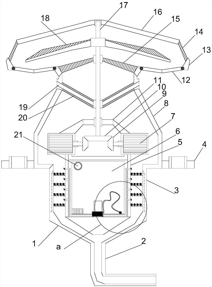
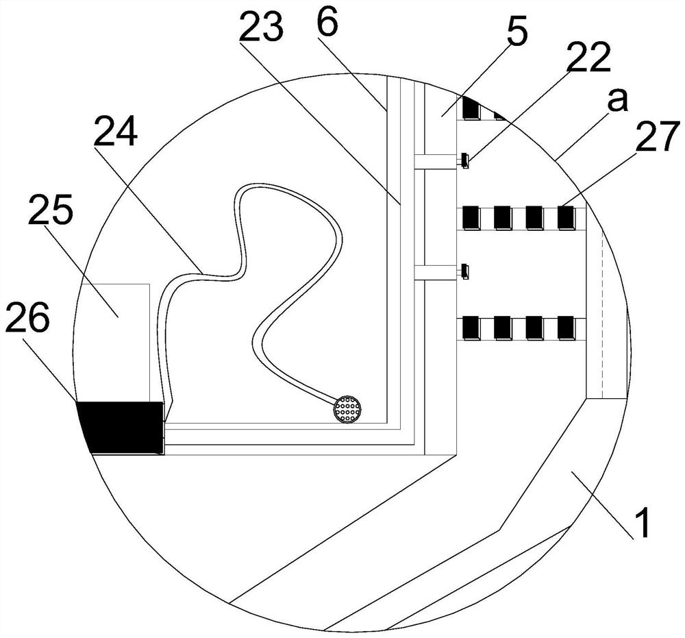
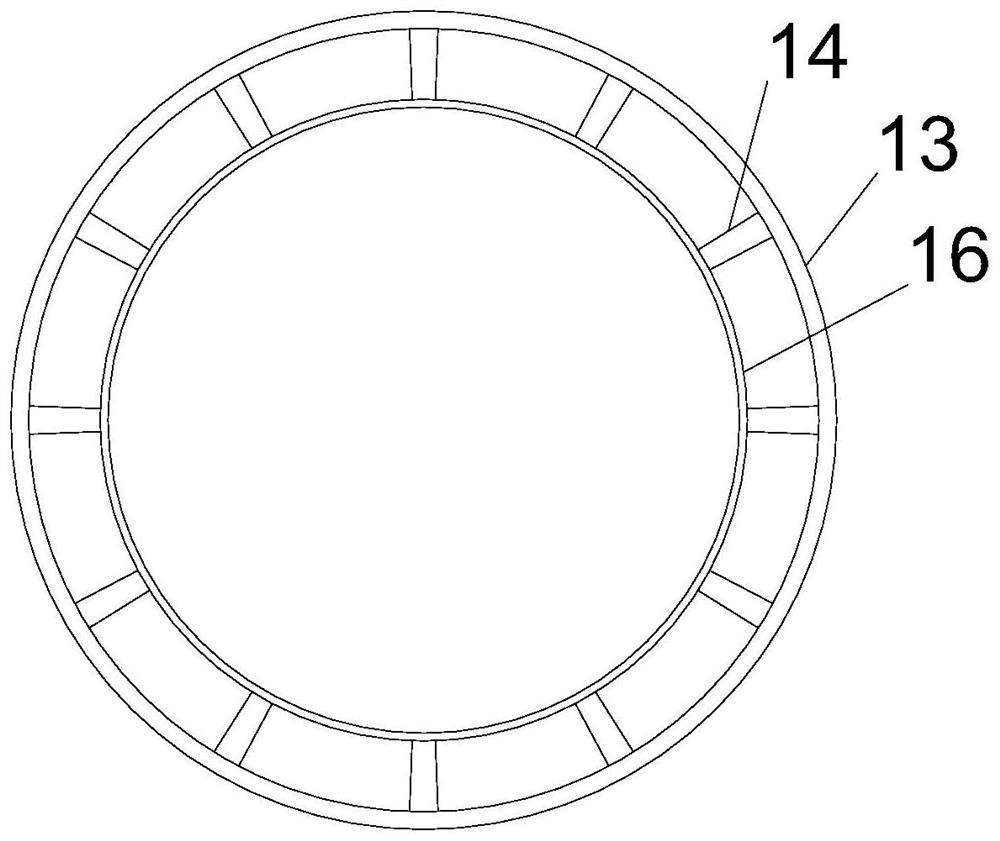
[0020] see Figure 1~4 , in the embodiment of the present invention, a draft type waste gas treatment device includes a vertically arranged variable-diameter installation cylinder 8, and a guide installation cylinder 3 is arranged vertically downward at the middle position of the lower end of the variable-diameter installation cylinder 8. The middle position of the upper end of the diameter installation cylinder 8 is vertically provided with an active shaft 17...


PUM


Abstract

The invention discloses a draft type waste gas treatment device, which comprises a vertically arranged variable-diameter installation cylinder. The position of the diversion installation column set at an equal angle and the bearing sleeve installed vertically in the middle position are vertically equipped with an active shaft, and the upper end of the variable-diameter installation cylinder is coaxial with the horizontal coaxial installation of the active shaft. A wind-collecting installation cover is installed. The upper edge of the upper edge is equipped with a collecting cover plate through the diversion support column arranged at an equal angle, and the wind collecting installation cover outside the diversion installation column is equipped with an elastic reset blanking structure at an equal angle, and the lower end of the active shaft is matched with the variable diameter installation cylinder. The shaft is equipped with a cone-top power installation cylinder. The invention has the advantages of compact structure design, simple installation and fixation, adopting the design of drafting and diversion, good interchangeability, and high efficiency of waste gas treatment.

Description

technical field [0001] The invention relates to a waste gas treatment device, in particular to a ventilation type waste gas treatment device. Background technique [0002] In addition to the production of products, industrial production is also accompanied by the generation of waste gas and waste. Waste is easier to collect and utilize, but waste gas collection is difficult and harmful to the environment. People pay more and more attention to the treatment of waste gas. However, the currently used waste gas treatment devices, The design is not perfect, and the collection is not perfect, and there are various problems in actual use. [0003] In order to solve the above problems, the present invention is proposed, which overcomes the problems of insufficient waste gas treatment and long processing time due to the use of simple filter element filtration or water aeration method, and solves the problems of the currently used waste gas treatment device. The treatment device adop...

Claims


Application Information

Patent Timeline
Patent Type & Authority Patents(China)
IPC IPC(8): B01D50/00B01D53/18
CPCB01D53/18B01D50/60
Inventor 吴烨程
Owner TANGSHAN LUAN SHUO INORGANIC SILICIDE LTD
Features
  • R&D
  • Intellectual Property
  • Life Sciences
  • Materials
  • Tech Scout
  • Unparalleled Data Quality
  • Higher Quality Content
  • 60% Fewer Hallucinations
Learn More