Steel bar cutter for bridge construction

A steel bar cutting machine and bridge construction technology, applied in metal processing, manufacturing tools, metal processing equipment, etc., can solve the problems of high use limitations, low safety factor, and easy danger, so as to liberate manpower and improve use limitations , Improve the effect of safety factor

Inactive Publication Date: 2018-08-28
山西云度知识产权服务有限公司
View PDF6 Cites 0 Cited by
  • Summary
  • Abstract
  • Description
  • Claims
  • Application Information

AI Technical Summary

Problems solved by technology

[0002] As we all know, the steel bar cutting machine for bridge construction is a kind of auxiliary device used for steel bar processing and cutting to facilitate the better construction of bridge engineering. It has been widely used in the field of bridge manufacturing and reinforcement; the existing bridge The steel bar cutting machine for construction includes a workbench, a support arm, a connecting rod and a cutting hydraulic cylinder. The top of the connecting rod is connected to the bottom end of the connecting rod, and the bottom output end of the cutting hydraulic cylinder is provided with a cutting hydraulic rod. Below the cutter head; when using the existing steel bar cutting machine for bridge construction, first measure the required steel bar length and mark it, then place the marked steel bar on the upper surface of the workbench, and place the marked position on the cutter head Just below the cutting machine, and then open the hydraulic cylinder, the extension of the hydraulic rod drives the cutter head to move vertically downward, the cutter head moves to the knife groove, and the steel bar is cut off; in the use of the existing steel bar cutting machine for bridge construction, it is found that the steel bar is on the workbench Manual pressing is required. When the cutter head moves downward, the two ends of the steel bar will be lifted due to the force on the mark of the steel bar. When the manpower is insufficient, it is prone to danger and the safety factor is low; Reinforcement bars, high limitations of use

Method used


Image

  • Steel bar cutter for bridge construction
  • Steel bar cutter for bridge construction
  • Steel bar cutter for bridge construction

Examples


Embodiment Construction

[0021] The specific implementation manners of the present invention will be further described in detail below in conjunction with the accompanying drawings and embodiments. The following examples are used to illustrate the present invention, but are not intended to limit the scope of the present invention.

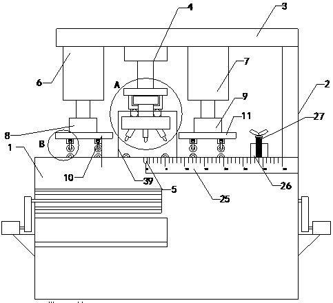
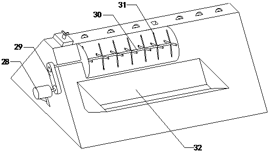
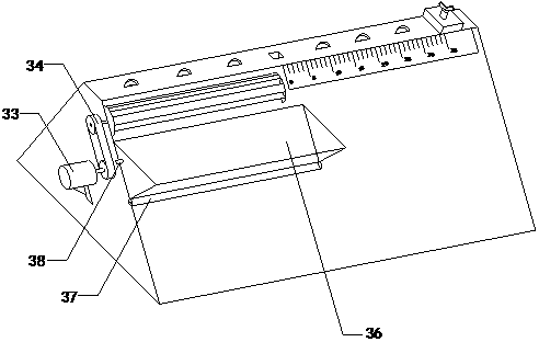
[0022] like Figure 1 to Figure 7As shown, a steel bar cutting machine for bridge construction of the present invention includes a workbench 1, a support arm 2, a connecting rod 3 and a cutting hydraulic cylinder 4, the bottom end of the support arm is connected with the top right side of the workbench, and the The top is connected to the right bottom of the connecting rod, the top of the cutting hydraulic cylinder is connected to the bottom of the connecting rod, and the bottom output end of the cutting hydraulic cylinder is provided with a cutting hydraulic rod, and the middle part of the top of the table is also provided with a knife groove 5; including Left pressing h...


PUM


Abstract

The invention relates to the technical field of steel bar machining accessory devices, in particular to a steel bar cutter for bridge construction. The steel bar cutter can carry out automatic pressing and improve safety coefficients, different cutter bits can be switched, and using limitation is reduced. The steel bar cutter comprises a workbench, a branch arm, a connection rod and a cutting hydraulic cylinder, the middle of the top end of the workbench is provided with a cutter slot, a left pressing hydraulic cylinder, a right pressing hydraulic cylinder, a left connection plate, a right connection plate, a left pressing plate, a right pressing plate, a limiting plate, a supporting rod, an upper pulley and a lower pulley, the bottom ends of the upper pressing plate and the lower pressingplate are sleeved with casing pipes, cavities are formed in the casing pipes, and springs are arranged in the cavities. A top plate, a sleeve, a limiting shaft, a rotating shaft, a cutter replacing disc, the first cutter bit, the second cutter bit and the third cutter bit are further involved, a rotary ball bearing is arranged between the cutter replacing disc and the sleeve, the first cutter bit, the second cutter bit an the third cutter bit are located below the cutter replacing disc, and the top ends of the first cutter bit, the second cutter bit and the third cutter bit are connected withthe bottom end of the cutter replacing disc.

Description

technical field [0001] The invention relates to the technical field of steel bar processing attachments, in particular to a steel bar cutting machine for bridge construction. Background technique [0002] As we all know, the steel bar cutting machine for bridge construction is a kind of auxiliary device used for steel bar processing and cutting to facilitate the better construction of bridge engineering. It has been widely used in the field of bridge manufacturing and reinforcement; the existing bridge The steel bar cutting machine for construction includes a workbench, a support arm, a connecting rod and a cutting hydraulic cylinder. The top of the connecting rod is connected to the bottom end of the connecting rod, and the bottom output end of the cutting hydraulic cylinder is provided with a cutting hydraulic rod. Below the cutter head; when using the existing steel bar cutting machine for bridge construction, first measure the required steel bar length and mark it, then...

Claims


Application Information

Patent Timeline
Patent Type & Authority Applications(China)
IPC IPC(8): B21F11/00B21C51/00
CPCB21F11/00B21C51/00
Inventor 李有花
Owner 山西云度知识产权服务有限公司
Why Eureka
Try Eureka