Quick positioning demoulding device for casting iron pan pressure casting production

A technology of demoulding device and cast iron pot, which is applied in the field of rapid positioning and demoulding device for cast iron pot die-casting production, which can solve the problems that the mold cannot be positioned quickly and accurately, consumes energy, and is damaged

Pending Publication Date: 2018-08-28
HENAN ZHONGSHUAI METAL PROD CO LTD
View PDF5 Cites 2 Cited by
  • Summary
  • Abstract
  • Description
  • Claims
  • Application Information

AI Technical Summary

Problems solved by technology

[0003] In the production process of cast iron pots, die-casting production will be used. In the existing technology, the mold cannot be positioned quickly and accurately, which will cause the die-casted products to become defective products that need to be re-melted and die-cast, which consumes a lot of energy; secondly, during the demoulding process, Easy to cause cracks or breakage, demoulding failure

Method used


Image

  • Quick positioning demoulding device for casting iron pan pressure casting production
  • Quick positioning demoulding device for casting iron pan pressure casting production
  • Quick positioning demoulding device for casting iron pan pressure casting production

Examples


Embodiment 1

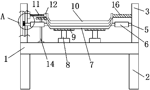
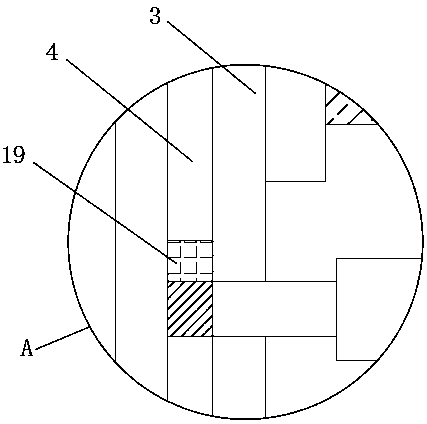
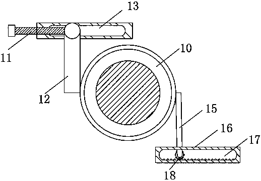
[0024] A rapid positioning and demoulding device for cast iron pot die-casting production, including a workbench 1 and legs 2, the lower end of the workbench 1 is fixedly connected with the outrigger 2, and the upper surface of the workbench 1 is fixedly installed with two sets of fixing plates 3, the fixing plates 3 The middle part is provided with a damping chute 4, and the damping chute 4 is fixedly connected with the first fixed rod 5 through a slider, the outer surface of the first fixed rod 5 is provided with a heat insulating sleeve 6, and the end of the first fixed rod 5 is connected with a lower mold 7 The upper end of the workbench 1 is located below the lower mold 7, and a hydraulic lifting device 8 is fixedly installed, and an upper mold 10 is arranged above the lower mold 7. An electric push rod 11 is fixedly installed on the upper part of a group of fixed plates 3, and the end of the electric push rod 11 is fixedly connected. The sliding rod 12, the lower end of t...

Embodiment 2

[0026] A rapid positioning and demoulding device for cast iron pot die-casting production, including a workbench 1 and legs 2, the lower end of the workbench 1 is fixedly connected with the outrigger 2, and the upper surface of the workbench 1 is fixedly installed with two sets of fixing plates 3, the fixing plates 3 The middle part is provided with a damping chute 4, and the damping chute 4 is fixedly connected with the first fixed rod 5 through a slider, the outer surface of the first fixed rod 5 is provided with a heat insulating sleeve 6, and the end of the first fixed rod 5 is connected with a lower mold 7 The upper end of the workbench 1 is located below the lower mold 7, and a hydraulic lifting device 8 is fixedly installed, and an upper mold 10 is arranged above the lower mold 7. An electric push rod 11 is fixedly installed on the upper part of a group of fixed plates 3, and the end of the electric push rod 11 is fixedly connected. The sliding rod 12, the lower end of t...

Embodiment 3

[0029] A rapid positioning and demoulding device for cast iron pot die-casting production, including a workbench 1 and legs 2, the lower end of the workbench 1 is fixedly connected with the outrigger 2, and the upper surface of the workbench 1 is fixedly installed with two sets of fixing plates 3, the fixing plates 3 The middle part is provided with a damping chute 4, and the damping chute 4 is fixedly connected with the first fixed rod 5 through a slider, the outer surface of the first fixed rod 5 is provided with a heat insulating sleeve 6, and the end of the first fixed rod 5 is connected with a lower mold 7 The upper end of the workbench 1 is located below the lower mold 7, and a hydraulic lifting device 8 is fixedly installed, and an upper mold 10 is arranged above the lower mold 7. An electric push rod 11 is fixedly installed on the upper part of a group of fixed plates 3, and the end of the electric push rod 11 is fixedly connected. The sliding rod 12, the lower end of t...


PUM


Abstract

The invention discloses a quick positioning demoulding device for casting iron pan pressure casting production. The quick positioning demoulding device comprises a working table and landing legs, thelower end of the working table is fixedly connected with the landing legs, the upper surface of the working table is fixedly provided with two sets of fixing plates, a damping sliding groove is formedin the middle portion of each fixing plate and is fixedly connected with a first fixing rod through a sliding block, and an insulation cover is arranged on the outer surface of each first fixing rod.The quick positioning demoulding device is provided with the damping sliding grooves and the sliding blocks, a lower mold can be driven to move up and down quickly, limiting blocks limit the slidingblocks, and the lower mold can move to the same position each time; and a hydraulic lifting device and a support plate apply pressure to the lower mold to promote quick molding of a casting iron pan.A linear actuator is arranged to push a sliding rod to slide horizontally, an upper mold is further driven to rotate clockwise, a driven rod is stressed to drive a gear to move along a toothed groove,the upper mold rotates back and forth to quickly separate from the casting iron pan through reciprocating motion, and demoulding is accelerated.

Description

technical field [0001] The invention relates to the technical field of demoulding devices, in particular to a quick-positioning demoulding device for die-casting production of cast iron pots. Background technique [0002] Die-casting is a metal casting process, which is characterized by applying high pressure to the molten metal using the cavity of the mold. Die-casting is especially suitable for manufacturing a large number of small and medium-sized castings, so die-casting is the most widely used among various casting processes. Compared with other casting technologies, die casting has a flatter surface and higher dimensional consistency. [0003] In the production process of cast iron pots, die-casting production will be used. In the existing technology, the mold cannot be positioned quickly and accurately, which will cause the die-casted products to become defective products that need to be re-melted and die-cast, which consumes a lot of energy; secondly, during the demo...

Claims


Application Information

Patent Timeline
Patent Type & Authority Applications(China)
IPC IPC(8): B22D17/22
CPCB22D17/2236
Inventor 张信卿张永辉汪小平张金岭张亚辉
Owner HENAN ZHONGSHUAI METAL PROD CO LTD
Why Eureka
Try Eureka