
Rotary pipe welder

A pipe welding machine and rotary technology, which is applied in the field of steel pipe welding, can solve the problems of affecting the welding quality, affecting the welding efficiency of the pipe welding machine, affecting the convenience of the pipe welding machine, etc., and achieving the effect of convenient and rapid welding.

Inactive Publication Date: 2018-08-28
邱福祥
View PDF0 Cites 2 Cited by
  • Summary
  • Abstract
  • Description
  • Claims
  • Application Information

AI Technical Summary

Problems solved by technology

[0004] The purpose of the present invention is to provide a rotary pipe welding machine to solve the problem that when the existing welded steel pipe is used, the manually fixed steel pipe tends to move during the welding process, which affects the welding quality, and the fixed plate blocks the ring welding of the welding torch, and the welding torch is difficult to adjust. The steel pipe is welded in all directions, and the welding torch is difficult to align with the gap to be welded and needs to be held by the user, which affects the convenience of using the pipe welding machine. In addition, when the steel pipe is too long, it is difficult to fix it effectively, which affects the welding efficiency of the pipe welding machine

Method used


Image

  • Rotary pipe welder
  • Rotary pipe welder
  • Rotary pipe welder

Examples


Embodiment Construction

[0022] The following will clearly and completely describe the technical solutions in the embodiments of the present invention with reference to the accompanying drawings in the embodiments of the present invention. Obviously, the described embodiments are only some, not all, embodiments of the present invention. Based on the embodiments of the present invention, all other embodiments obtained by persons of ordinary skill in the art without making creative efforts belong to the protection scope of the present invention.

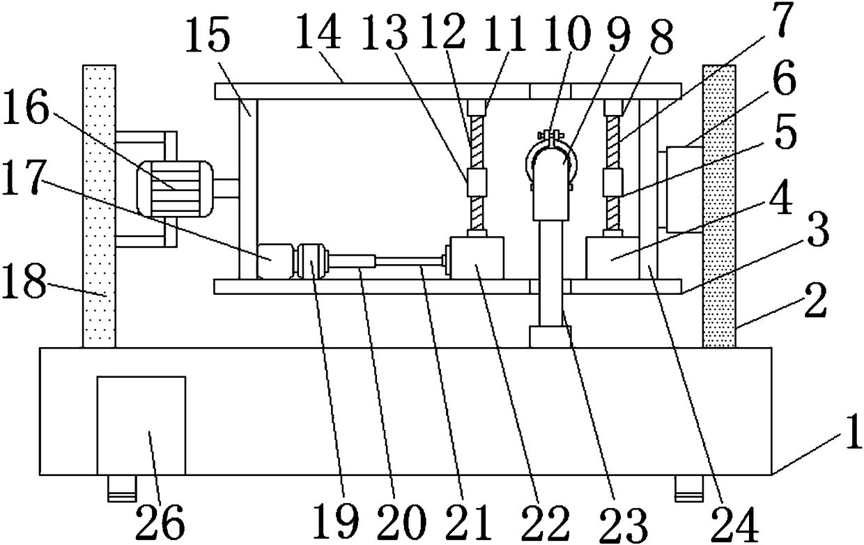
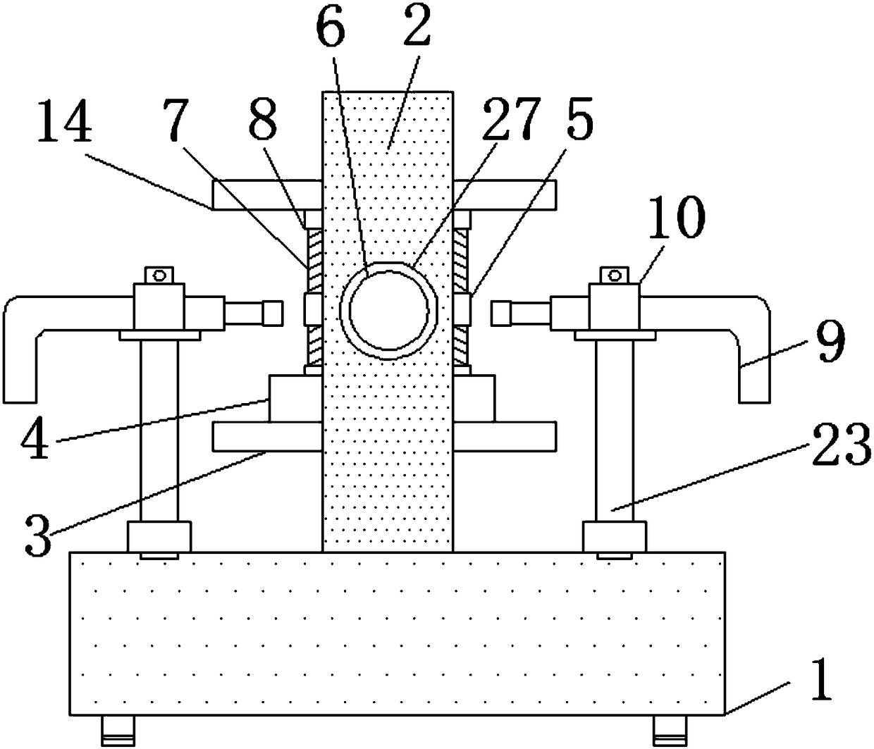
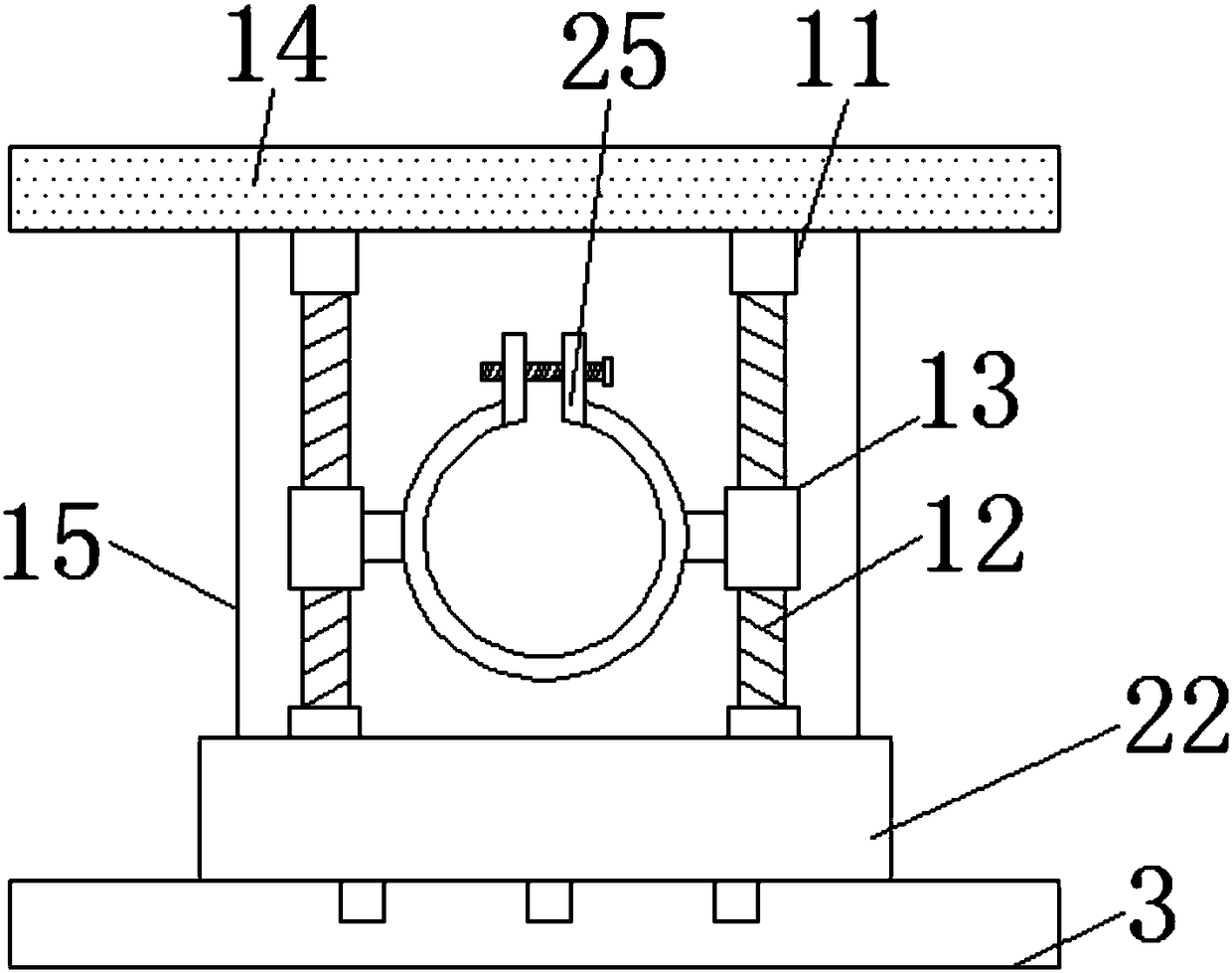
[0023] see Figure 1-5 , the present invention provides the following technical solutions: a rotary pipe welding machine, including a base 1, a first support plate 2 is installed on the top of the base 1, a circular through groove 27 is opened inside the first support plate 2, and the circular through groove The inside of 27 is fixedly connected with the connecting rod bearing 6, the inside of the connecting rod bearing 6 is fixedly connected with the connecti...


PUM


Abstract

The invention discloses a rotary pipe welder which comprises a base. A first supporting plate is mounted at the top end of the base. A round through groove is formed in the first supporting plate. A connecting rod bearing is fixedly connected in the round through groove. A connecting rod is fixedly connected in the connecting rod bearing through a fixed ring. The top end of the connecting rod is fixedly connected with a top end fixed plate. According to the rotary pipe welder, a second adjusting seat, a second lead screw and a second lead screw pair ring sleeve are arranged, when the pipe welder is used, a user can fix another steel pipe needing to be welded to the inner side of a fixed clamp on one side of the second lead screw pair ring sleeve, the second adjusting seat is rotated to drive the second lead screw to rotate, the second lead screw drives the second lead screw pair ring sleeve to move in the vertical direction, and therefore the positions of another unthreaded steel pipeand the steel pipe to be welded are adjusted; and the problems that during steel pipe welding, the steel pipes are manually fixed and are prone to moving in the welding process, and the welding quality is influenced are avoided.

Description

technical field [0001] The invention belongs to the technical field of steel pipe welding, and in particular relates to a rotary pipe welding machine. Background technique [0002] Pipe welding machines are usually used to weld various metal pipes, usually with complex structures. During the welding process, it can effectively weld the position to be welded. It is often used in mechanized welding in the industrial field to achieve the accuracy that manual welding does not have. [0003] However, when using the existing welded steel pipe, the manually fixed steel pipe tends to move during the welding process, which affects the welding quality, and the fixed plate blocks the ring welding of the welding torch, which makes it difficult for the welding torch to weld all directions of the steel pipe The welding gap needs to be held by the user, which affects the convenience of the pipe welding machine. In addition, when the steel pipe is too long, it is difficult to fix it effecti...

Claims


Application Information

Patent Timeline
Patent Type & Authority Applications(China)
IPC IPC(8): B23K37/02B23K37/053
CPCB23K37/027B23K37/0229B23K37/0538
Inventor 邱福祥
Owner 邱福祥
Learn More