
Mechanical device for truck loading

A technology of a mechanical device and a main body is applied in the field of mechanical devices for loading vehicles, which can solve the problems of poor water replenishment effect, internal water loss, and height drop of loaded goods, so as to avoid waste caused by water flow, reduce water flow consumption, and reduce height drop. Effect

Inactive Publication Date: 2018-08-28
周洁
View PDF2 Cites 2 Cited by
  • Summary
  • Abstract
  • Description
  • Claims
  • Application Information

AI Technical Summary

Problems solved by technology

[0007] In order to solve the above technical problems, the present invention provides a mechanical device for loading vehicles to solve the retrieval based on the above two patents, as well as the discovery of equipment in the prior art. The use effect is poor, the interior of the compartment cannot be well illuminated, it is easy to affect the loading efficiency at night, and it is easy to form a height difference between the device and the interior of the compartment, causing the goods to fall from the device to the interior of the compartment, causing damage to the goods, and the function is relatively poor. Single, the effect of replenishing water on the loaded vegetables and fruits is poor. After the vegetables and fruits are transported for a long time, it is easy to cause internal water loss and affect the external appearance of vegetables and fruits.

Method used


Image

  • Mechanical device for truck loading
  • Mechanical device for truck loading
  • Mechanical device for truck loading

Examples


Embodiment

[0035] as attached figure 1 to attach Figure 8 Shown:

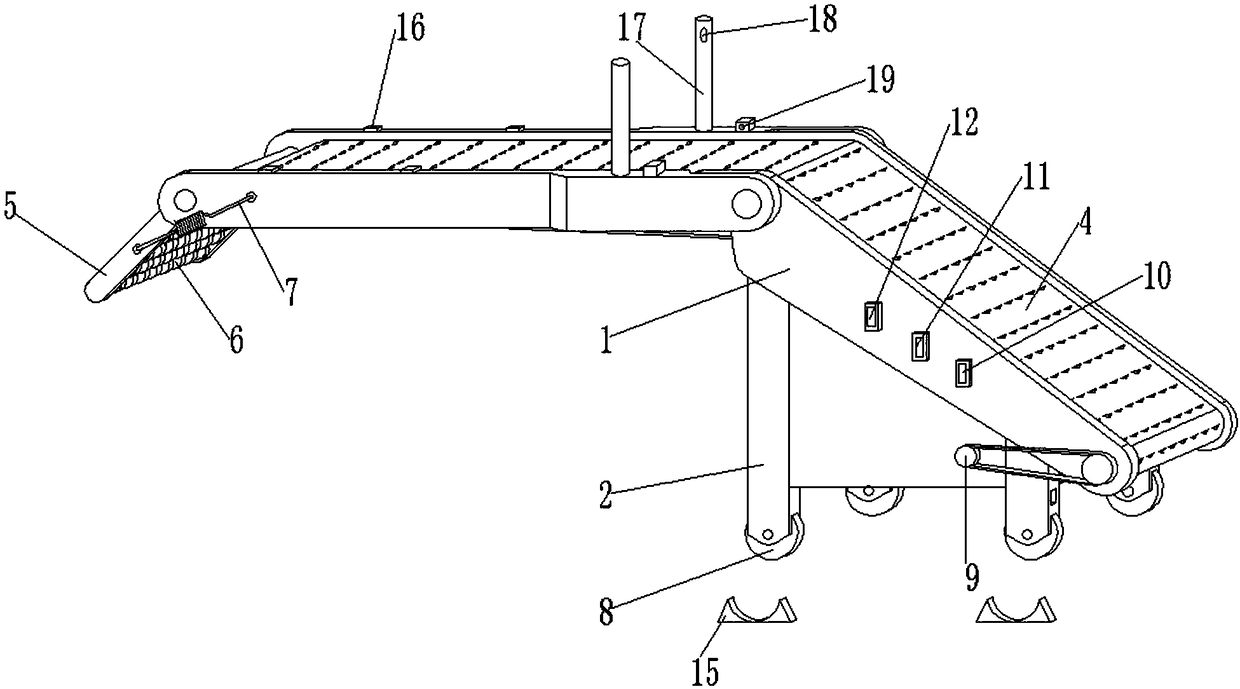
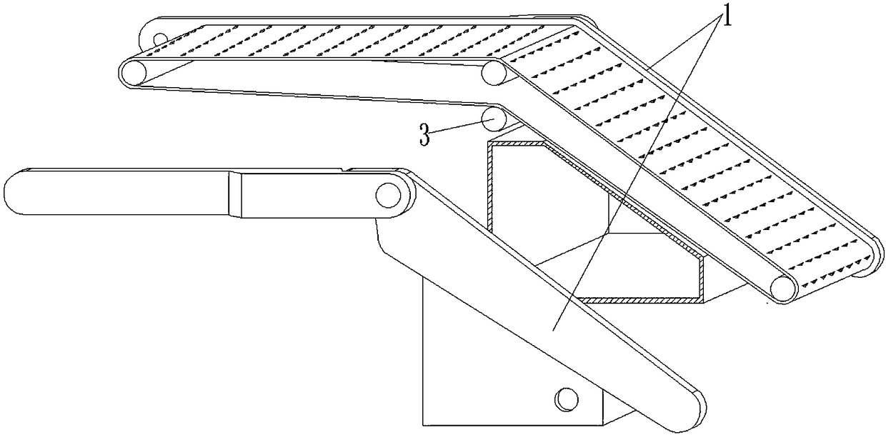
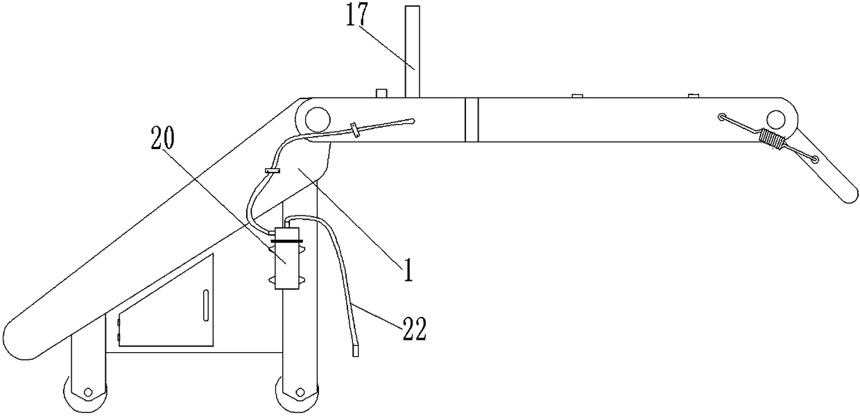
[0036]The present invention provides a mechanical device for loading vehicles, including a main body 1, a support frame 2, a rotating shaft 3, a conveyor belt 4, a prismatic rubber block 401, a rotating frame 5, a rotating bead 6, a tension spring 7, a rotating wheel 8, and a driving shaft 9 , conveyor belt running switch 10, lighting switch 11, sprinkler switch 12, battery 13, transmission motor 14, wheel fixing block 15, LED light 16, metal tube 17, atomizing head 18, photoelectric switch 19, water pump 20, controller 21 and Pipeline 22, four supporting frames 2 are installed at the bottom of the main body 1, and the four rotating shafts 3 are rotatably connected in the main body 1, the conveyor belt 4 is rotatably connected in the main body 1, and the rotary frame 5 is rotatably connected with the top front end of the main body 1, so The rotating bead 6 is several places, and the rotating bead 6 and the rotating bea...


PUM


Abstract

The invention provides a mechanical device for truck loading. The mechanical device for truck loading comprises a controller and a pipeline. Four support frames are arranged on the bottom part of a main body; four rotary shafts are rotatably connected into the main body; a conveyor belt is rotatably connected into the main body; a rotary frame is rotatably connected to the front end of the top part of the main body; multiple rotary balls are arranged and are serially connected through the rotary frame; four rotary wheels are arranged on the bottom parts of the four support frames; a driving shaft is arranged on a driving motor, is located on the left side end surface of the main body, and is in driving connection with the corresponding rotary shaft on the bottom part on which the driving shaft is arranged; a conveyor belt operation switch, a lighting switch and a watering switch are arranged on the left side end surface of the main body, so that containers on the conveyor belt can be favorably stopped so as to be prevented from falling off from an inclined slope part to influence the container operation efficiency; and by the cooperative use of wheel fixing blocks, the bottom partof the device can be fixed, so that the device can be prevented from moving left and right to influence the container loading efficiency.

Description

technical field [0001] The invention belongs to the technical field of vehicle loading machinery, and more specifically relates to a mechanical device for vehicle loading. Background technique [0002] At present, when unloading and loading trucks, most manufacturers use forklifts to move the goods, but when encountering some goods that do not have preset forklift holes, they use manual handling, and the uneven cost of manual handling is high, and it is easy to Handling causes items to affect the efficiency of unloading and loading. [0003] Based on the above, the inventors found that there are existing similar devices, such as the Chinese patent application No. 201510003047.8, which mentions an automatic loading device suitable for vans, including telescopic conveyors, slope conveyors, universal moving Platform, two-way movement mechanism, code bag conveyor, in which the telescopic conveyor is located at the rear of the whole device, the front outlet of the telescopic con...

Claims


Application Information

Patent Timeline
IPC IPC(8): B65G67/08
CPCB65G67/08
Inventor 周洁李华杨海龙
Owner 周洁
Learn More