Dynamic monitoring device and monitoring method for CO leaking of industrial equipment

A technology for industrial equipment and dynamic monitoring, applied in lighting and heating equipment, by detecting the appearance of fluid at the leak point, using liquid/vacuum for liquid tightness measurement, etc. , cumbersome and other problems, to achieve the effect of small operation space occupation, simple monitoring method and broad market prospect

Active Publication Date: 2018-08-28
ZHONGYE-CHANGTIAN INT ENG CO LTD
View PDF6 Cites 2 Cited by
  • Summary
  • Abstract
  • Description
  • Claims
  • Application Information

AI Technical Summary

Problems solved by technology

[0004] 1. Small monitoring range: In the existing technology, a CO detector is generally installed at a certain point of the equipment. This method can only monitor the relevant parameters of a small part of the industrial equipment. The monitoring range is very small and cannot reflect the real situation. Reduce the safety factor of industrial equipment and bring great hidden dangers to the personal safety of operators
However, if CO detectors are installed at multiple points of industrial equipment, the cost will be too high and the operating space of industrial equipment will be greatly reduced
[0005] 2. Occupy the operating space of industrial equipment: the CO detector needs to be connected with signal cables and power cables to operate normally, and the cables need to be covered with steel pipes. These additional equipment will greatly occupy limited operating space, and when the operator is operating, It is very easy to trip over the steel pipe with the cable jacket and cause production accidents
[0006] 3. Unable to predict the location of CO leakage: under the existing technology, when the CO detector detects CO leakage, the system cannot predict the location of CO leakage
If you want to know the CO leakage point, the operator has to take a portable CO detector to test the location one by one, which is cumbersome and increases the labor intensity

Method used


Image

  • Dynamic monitoring device and monitoring method for CO leaking of industrial equipment
  • Dynamic monitoring device and monitoring method for CO leaking of industrial equipment
  • Dynamic monitoring device and monitoring method for CO leaking of industrial equipment

Examples


Embodiment 1

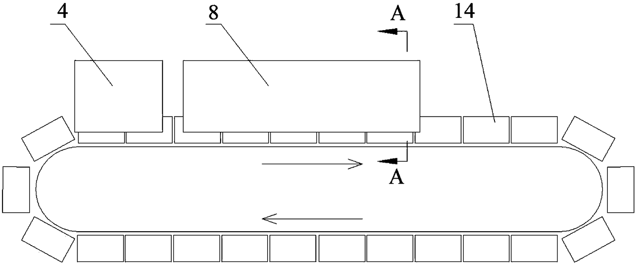
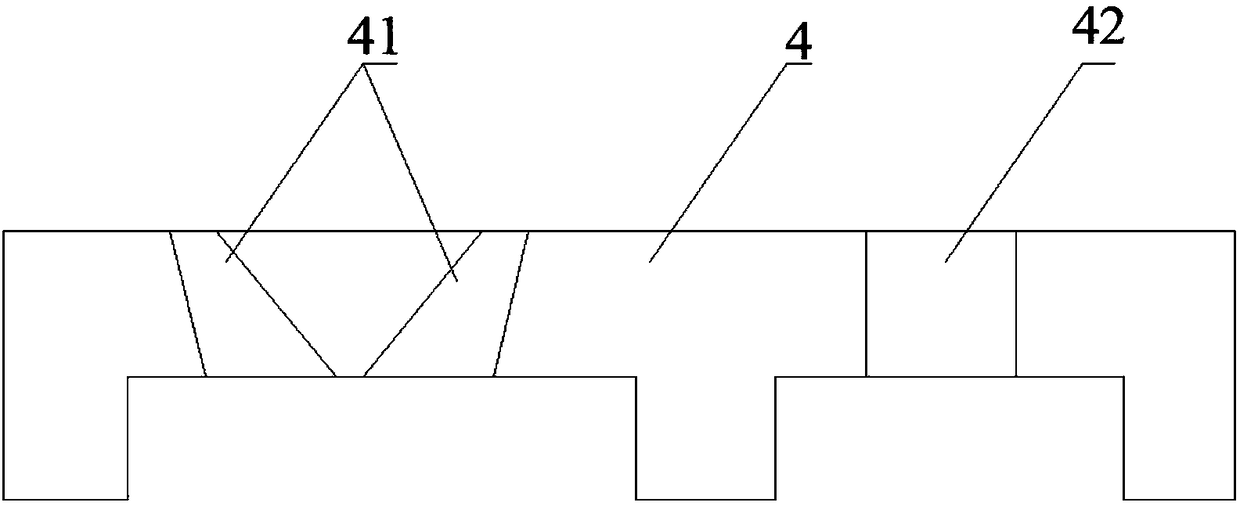
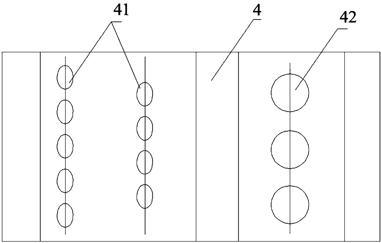
[0057] Such as Figure 1-3 , Figure 6 As shown, the dynamic monitoring device for CO leakage of sintering equipment in this embodiment, the sintering equipment includes an ignition furnace 4, a gas injection device 8 and a sintering equipment trolley 14, and the ignition furnace 4 includes two rows of ignition burners 41 and a row of heat preservation burners. nozzle 42 , the gas injection device 8 includes a gas injection cover 81 and a gas injection pipeline 82 . At least one set of dynamic monitoring device is provided. The dynamic monitoring device includes a patrol device 1, a CO detector 21 and a controller 3. The track 12 on the furnace top and / or the top of the gas injection cover 81, the CO detector 21 is installed on the patrol robot 11, and the patrol robot 11 runs on the track 12 under the drive of the driving device, and the CO detector 21 will be on the ignition furnace 4 The monitoring signals received by the furnace top and / or the top of the gas injection ho...

Embodiment 2

[0074] Such as Figure 14 , Figure 15 As shown, the rotary kiln 7 valve group platform 73 dynamic monitoring device for CO leakage in this embodiment, the rotary kiln 7 includes a kiln body, a burner device for heating the kiln body and a driving device for driving the kiln body to rotate, the burner device includes a central A burner 72 and a valve group platform 73 for supplying fuel to the central burner 72 . The dynamic monitoring device includes a patrol device 1, a CO detector 21 and a controller 3. The patrol device 1 includes a patrol robot 11, a driving device (including a driving motor and a traveling wheel 26) and a track 12 arranged on the upper part of the valve group platform 73, and the CO detection The instrument 21 is installed on the patrol robot 11, and the patrol robot 11 runs on the track 12 driven by the driving device. The CO detector 21 transmits the monitoring signal received on the upper part of the valve group platform 73 to the controller 3 in rea...

Embodiment 3

[0090] Such as Figure 19 As shown, the dynamic monitoring device for CO leakage of the lime shaft kiln 9 of the present embodiment, the lime shaft kiln 9 includes a shaft kiln body 91, a feeding device 92 and a blower device 93, and the feeding device 92 is arranged on the top of the shaft kiln body 91, The blast device 93 is arranged at the bottom of the shaft kiln body 91. The dynamic monitoring device includes a patrol device 1, a CO detector 21 and a controller 3. The patrol device 1 includes a patrol robot 11, a driving device (including a driving motor and a walking wheel 26) and The track 12 arranged around the shaft kiln body 91, the CO detector 21 is installed on the patrol robot 11, and the patrol robot 11 runs on the track 12 under the drive of the driving device, and the CO detector 21 will receive the CO detector around the shaft kiln body 91 The monitoring signal is transmitted to the controller 3 in real time.

[0091] In this embodiment, the patrol device 1 i...


PUM


Abstract

The invention discloses a dynamic monitoring device for CO leaking of industrial equipment. The dynamic monitoring device comprises a patrol device, a CO detector and a controller. The patrol device comprises a patrol robot, a drive device and a rail arranged at the CO leaking to-be-monitored position of the industrial equipment. The CO detector is mounted on the patrol robot. The patrol robot runs on the rail under drive of the drive device. The CO detector transmits a monitoring signal received at the to-be-monitored position to the controller in real time. The invention further provides a monitoring method of the dynamic monitoring device. The dynamic monitoring device is wide in monitoring range and small in occupied operation space, the monitoring method is simple and convenient, andthe monitoring efficiency is high.

Description

technical field [0001] The invention belongs to the field of industrial equipment danger monitoring, in particular to a dynamic monitoring device and monitoring method for industrial equipment danger. Background technique [0002] CO leakage from industrial equipment needs to be monitored during modern sintering processes. The existing conventional method is to install a CO detector on a fixed point of the equipment, and then connect the CO detector to the central control room through signal cables, power cables, etc. During production, the CO detector will monitor the relevant parameters of the equipment in real time. If the set safety value is exceeded, the alarm horn will be sounded and an alarm signal will be sent to the central control room to inform the operators to stay away from the equipment that may have CO leakage. [0003] The conventional practice at this stage usually has the following three defects in actual production and application. [0004] 1. Small moni...

Claims


Application Information

Patent Timeline
Patent Type & Authority Applications(China)
IPC IPC(8): F27D21/00F27D21/04G01M3/04
CPCF27D21/00F27D21/04G01M3/04
Inventor 周浩宇向锡炎刘前
Owner ZHONGYE-CHANGTIAN INT ENG CO LTD
Why Eureka
Try Eureka