Strapdown inertial navigation system shaking pedestal systematic calibration method

A system-level calibration and strapdown inertial navigation technology, which is applied in the field of system-level calibration on the swaying base of the strapdown inertial navigation system, can solve the problems of inability to achieve calibration, high requirements for the intersecting degree of the rotary shaft of the turntable, and the solidification of the initial attitude rotation sequence, etc. question

Active Publication Date: 2018-08-28
BEIJING INST OF COMP TECH & APPL
View PDF6 Cites 16 Cited by
  • Summary
  • Abstract
  • Description
  • Claims
  • Application Information

AI Technical Summary

Problems solved by technology

[0004] The system-level calibration method based on kalman filtering has some disadvantages: (1) This method is suitable for high-precision inertial navigation (gyro bias stability is better than 0.1° / h), and the effect is not good for medium-precision inertial navigation; (2) only It can be realized on the turntable, manual flipping is not possible, and the requirements for the intersection degree of the turntable shafts are relatively high; (3) The observability analysis of this method is complicated, and it is difficult to arrange the rotation sequence in the calibration process; (4) The rotation of the calibration process The errors caused by the internal lever arm effect, external lever arm effect, gyroscope and accelerometer data asynchrony will seriously affect the calibration accuracy
[0008] However, the current system-level calibration based on least squares identification needs to meet three requirements in the application: (1) During the calibration process, the inertial navigation must be in a static state at other times except when it is overturned; (2) Horizontal and north orientation references are required The error is within 3°; (3) The initial attitude and rotation sequence of the inertial navigation system are fixed and cannot be changed, otherwise the calibration cannot be achieved
[0009] For these three requirements, it is more stringent in practical application and it is more difficult to fully meet them.
[0010] For example, for the first condition, when the inertial navigation system is installed on a carrier such as a vehicle, ship, or aircraft for system-level calibration, it is often affected by gusts of wind, engine vibration, surges, and people walking around, causing the carrier to shake angularly. As a result, the inertial navigation system is often in a state of angular shaking during the non-turnover time, which seriously affects the calibration accuracy and even causes calibration failure.
[0011] For the second condition, the parking attitude of the carrier is generally affected by the environment in which the carrier is located, and it cannot be guaranteed that the horizontal and north azimuth reference errors are within 3°. Therefore, this condition is also difficult to meet in practical applications.
[0012] For the third condition, the requirements for the initial attitude and rotation sequence of the inertial navigation system are relatively rigid, resulting in the inability to operate in accordance with the corresponding requirements under certain conditions, and ultimately unable to complete the calibration
[0013] Due to these requirements of the existing system-level calibration method based on least squares identification, it is difficult to meet most conditions in practical applications, which limits the scope of application of this calibration method

Method used


Image

  • Strapdown inertial navigation system shaking pedestal systematic calibration method
  • Strapdown inertial navigation system shaking pedestal systematic calibration method
  • Strapdown inertial navigation system shaking pedestal systematic calibration method

Examples


Embodiment Construction

[0092] In order to make the purpose, content, and advantages of the present invention clearer, the specific implementation manners of the present invention will be described in further detail below in conjunction with embodiments.

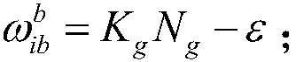
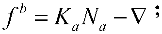
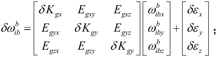
[0093] The first step is to establish an inertial navigation calibration compensation model

[0094] First, define the inertial coordinate system as the i system, and define the inertial navigation coordinate system as the b system. The three sensitive axes of the inertial navigation are X-axis, Y-axis, and Z-axis, and the X, Y, and Z axes are orthogonal to each other. Inertial navigation has three gyroscopes and three accelerometers, namely X gyroscope, Y gyroscope, Z gyroscope and X accelerometer, Y accelerometer, Z accelerometer, and X gyroscope and X accelerometer and b series The X axis coincides, the Y gyroscope and Y accelerometer coincide with the Y axis of the b system, and the Z gyroscope and Z accelerometer coincide with the Z axis of the b s...


PUM


Abstract

The invention discloses a strapdown inertial navigation system shaking pedestal systematic calibration method. The strapdown inertial navigation system shaking pedestal systematic calibration method comprises following steps: 1, an inertial navigation calibration compensation model is established; 2, an inertial navigation calibration compensation error model is established; 3, calibration sequence conversion arrangement and data acquisition are carried out; 4, calibration error calculating and correction are carried out, wherein the step 4 comprises following sub-steps: a, a northeast sky coordinate system of a location for calibration is taken as a navigation coordinate system; b, in overturning process time, attitude updating is carried out; c, in T1 time of a second location after overturning, open loop navigation attitude, position, and speed calculating are carried out; d, calculating of related matrix and error parameters is carried out; e, the overturning data from a second time to a 18th time is obtained through the sub-steps from a to d; f, calculating of calibration compensation error parameters is carried out; and h, iterative computation is carried out so as to obtainthe strapdown inertial navigation system shaking pedestal systematic calibration results. The strapdown inertial navigation system shaking pedestal systematic calibration method is invented based on least square identification method disadvantages, and is capable of realizing high precision calibration of inertial navigation at different initial attitudes and different overturning orders under baseless conditions.

Description

Technical field [0001] The present invention relates to the technical field of inertial navigation, in particular to a system-level calibration method on a sway base of a strapdown inertial navigation system. Background technique [0002] There are two main technical schemes for system-level calibration of strapdown inertial navigation system (hereinafter referred to as inertial navigation): (1) a system-level calibration scheme based on Kalman filtering; (2) a system-level calibration scheme based on least squares identification. [0003] The system-level calibration method based on Kalman filtering is to establish the error equation of the inertial navigation system, and list the error of the compensation parameter of the inertial navigation as the estimated state. By establishing the corresponding dimensional state equation and observation equation, supplemented by appropriate turntable operation, The Kalman filter is used to estimate and correct the error of the inertial naviga...

Claims


Application Information

Patent Timeline
Patent Type & Authority Applications(China)
IPC IPC(8): G01C25/00
CPCG01C25/005
Inventor 葛磊马仁冬王亚凯师兰芳李向东殷楠
Owner BEIJING INST OF COMP TECH & APPL
Why Eureka
Try Eureka