Distributed traveling wave monitoring terminal time deviation calculation and compensation method and system

A technology for monitoring terminal and time deviation, applied in the field of power equipment, can solve the problems of jumping change of deviation before and after time compensation, time deviation, and large time fluctuation, and achieves the effect of less resource occupation, easy engineering implementation, and low cost of software and hardware overhead.

Inactive Publication Date: 2018-08-28
EXAMING & EXPERIMENTAL CENT OF ULTRAHIGH VOLTAGE POWER TRANSMISSION COMPANY CHINA SOUTHEN POWER GRID
View PDF11 Cites 6 Cited by
  • Summary
  • Abstract
  • Description
  • Claims
  • Application Information

AI Technical Summary

Problems solved by technology

[0003] Due to different device locations, GPS second pulse time, device hardware and many other reasons, time deviation will be caused. It is necessary to calculate and compensate the deviation to improve the time accuracy. The current mainstream method is to judge the GPS second pulse per second and the device after the device is synchronized. Second pulse deviation, and then use the counter to compensate the deviation at a fixed position at one time. This method calculates the deviation per second and compensates it. It is easy to cause the deviation jump before and after time compensation, and the time fluctuation is large.

Method used


Image

  • Distributed traveling wave monitoring terminal time deviation calculation and compensation method and system
  • Distributed traveling wave monitoring terminal time deviation calculation and compensation method and system

Examples


Embodiment Construction

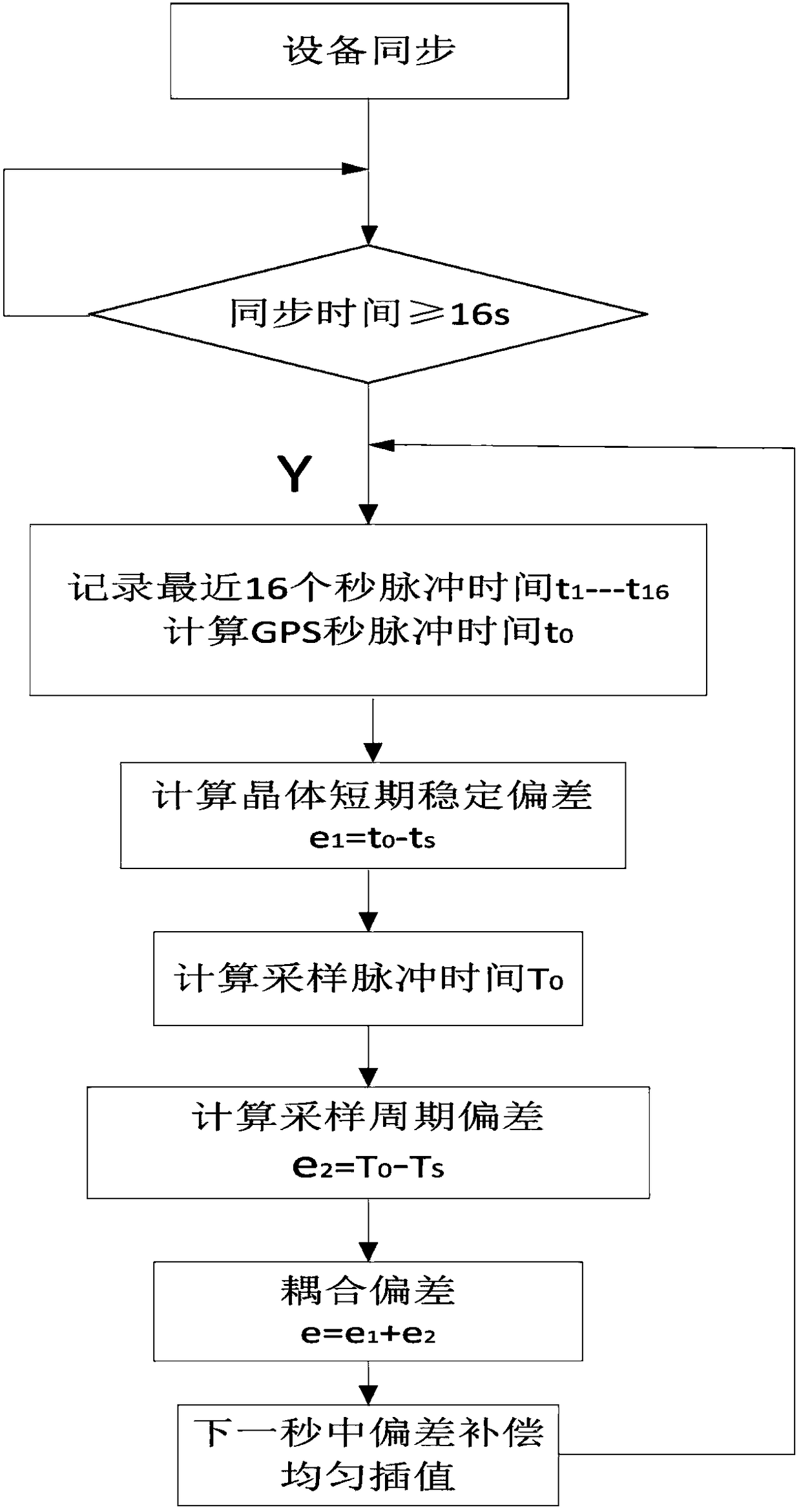
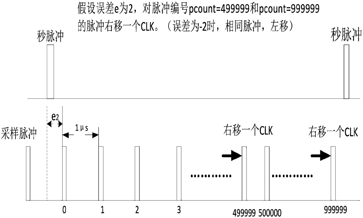
[0031] The present invention will be further described below in conjunction with the accompanying drawings and embodiments.

[0032] It should be pointed out that the following detailed description is exemplary and intended to provide further explanation to the present application. Unless defined otherwise, all technical and scientific terms used herein have the same meaning as commonly understood by one of ordinary skill in the art to which this application belongs.

[0033] It should be noted that the terminology used here is only for describing specific implementations, and is not intended to limit the exemplary implementations according to the present application. As used herein, unless the context clearly dictates otherwise, the singular is intended to include the plural, and it should also be understood that when the terms "comprising" and / or "comprising" are used in this specification, they mean There are features, steps, operations, means, components and / or combinatio...


PUM


Abstract

The present invention discloses a distributed traveling wave monitoring terminal time deviation calculation and compensation method and system. The method comprises the steps of: monitoring a GPS second pulse period after synchronization of a terminal device; calculating a crystal causing time deviation according to the measured actual second pulse period and the set second pulse ideal period; recording the measured actual second pulse phase difference to compare with a set phase difference to obtain phase deviation; and accumulating the time deviation and the phase deviation, and performing deviation compensation of an accumulated value. The distributed traveling wave monitoring terminal time deviation calculation and compensation method and system perform multi-time uniform compensationfor the time deviation compensation and achieve total-precision compensation.

Description

technical field [0001] The invention relates to the technical field of power equipment, in particular to a distributed traveling wave monitoring terminal time deviation calculation and compensation method and system. Background technique [0002] With the rapid development of the power industry, the scale of the power grid is expanding day by day, and the judgment of the fault location of the transmission line makes the distributed fault diagnosis system widely used. The distributed fault diagnosis system consists of distributed monitoring terminals installed on the transmission line conductor (or under the transmission line) and a background data center station. It is a system that can locate the fault point of the transmission line trip and identify the cause of the fault. The core idea of ​​the distributed fault diagnosis system is traveling wave ranging. The fault distance is calculated by measuring the time when the traveling wave current flows to the equipment at both ...

Claims


Application Information

Patent Timeline
Patent Type & Authority Applications(China)
IPC IPC(8): G01R31/08
CPCG01R31/085
Inventor 张怿宁孟令军王超金运昌王越杨
Owner EXAMING & EXPERIMENTAL CENT OF ULTRAHIGH VOLTAGE POWER TRANSMISSION COMPANY CHINA SOUTHEN POWER GRID
Why Eureka
Try Eureka