Dual-power switching protection device

A dual-power switching and protection device technology, applied in the direction of circuits, electric switches, electrical components, etc., can solve the problems of production work impact, easy generation of dust, and risk of circuit short circuit

Inactive Publication Date: 2018-08-28
STATE GRID SHANDONG ELECTRIC POWER CO YUNCHENG POWER SUPPLY CO
View PDF16 Cites 2 Cited by
  • Summary
  • Abstract
  • Description
  • Claims
  • Application Information

AI Technical Summary

Problems solved by technology

However, in the prior art, due to its processing technology, the surface of the circuit contact is prone to falling dust before contact. When the falling dust is easily scattered in an external ventilated environment, there is a possibility that the circuit may be short-circuited, causing serious damage to the actual production work. huge influence

Method used


Image

  • Dual-power switching protection device
  • Dual-power switching protection device

Examples


Embodiment 1

[0017] The following is a description of Embodiment 1.

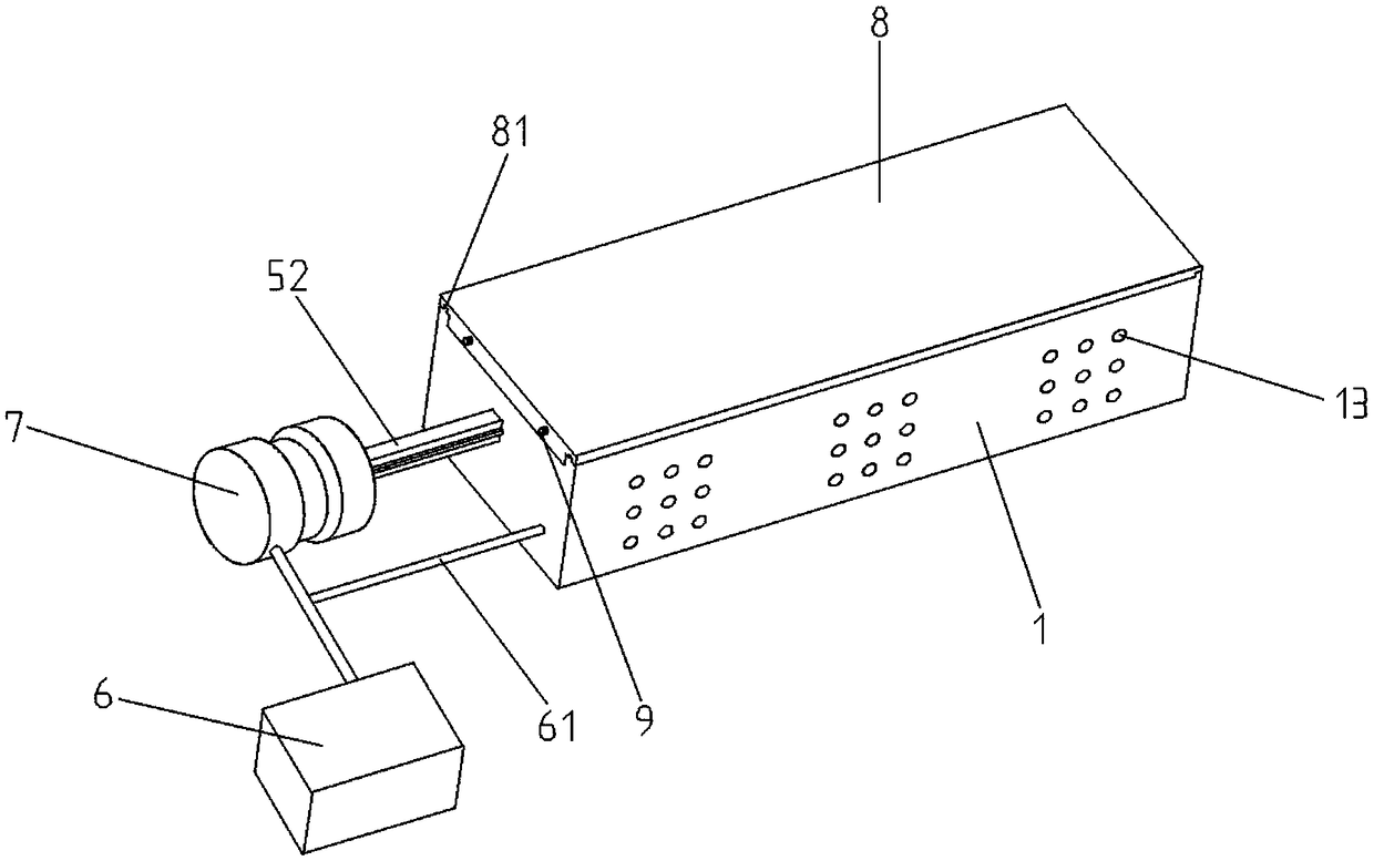
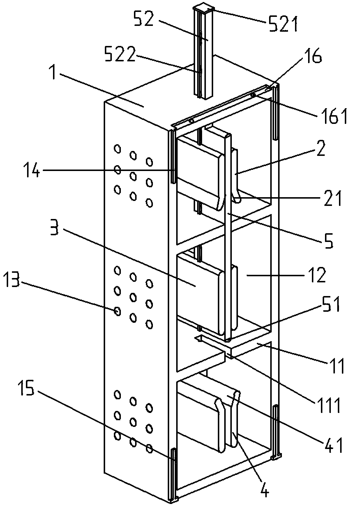
[0018] Such as Figure 1 to Figure 2 As shown, a dual power supply switching protection device includes a protective housing 1, a partition plate 11, a sliding channel 111, a working chamber 12, a cooling hole 13, a positioning slider 14, a mounting slider 15, a matching groove 16, and a mounting threaded hole 161. Main static contact piece 2, main entrance slot 21, output static contact piece 3, backup static contact piece 4, backup inlet slot 41, moving contact piece 5, anti-wear round convex 51, spare moving contact piece 52, limit plate 521, working slider 522, controller 6, control circuit 61, drive cylinder 7, protection end cover 8, installation chute 81, installation bolt 9, the inside of the protection shell 1 is provided with a cavity, and the cavity The cavity extends to the end surface of one side of the protective shell 1 to form an opening, the sides of the opening are respectively provided with positionin...

Embodiment 2

[0022] The following is a description of Embodiment 2.

[0023] In embodiment 2, for the same structure as in embodiment 1, the same symbols are given, and the same description is omitted. Embodiment 2 is improved on the basis of embodiment 1. The protective shell 1 is provided with A monitoring device, the monitoring device is connected with a controller, and the controller is connected with a display device.

[0024] When the device is in use, the moving contact piece 5 is in contact with the main static contact piece 2 and the output static contact piece 3 respectively. When any of the main static contact piece 2 and the output static contact piece 3 fails, the controller 6 controls the driving cylinder 7 to Spare movable contact piece 52, make the lower half of movable contact piece 5 contact with spare static contact piece 4, the upper half section of movable contact piece 5 contacts with output static contact piece 3, spare movable contact piece 52 contacts with main sta...


PUM


Abstract

The invention discloses a dual-power switching protection device, and belongs to the technical field of the power protection. The protection device comprises a protection shell, a movable contact, a controller, and a driving cylinder; a cavity is formed in the protection shell, a protection end cover is arranged at the cavity of the protection shell, and a partition plate is arranged in the cavityin the protection shell to divide the cavity into a working cavity; main static contacts, output static contacts and standby static contacts are respectively arranged in the working cavity from top to the bottom; two main static contacts, two output static contacts and two standby static contacts are provided, and the gaps are formed between two main static contacts, between two output static contacts and between two standby static contacts; the movable contact is arranged in the gap in a sliding way, a standby movable contact is arranged at the top of the movable contact, a sliding channel is formed on the partition plate, and the standby movable contact is cooperated on the protection shell and the partition plate; one side of a stop plate is connected with a driving cylinder, the controller is electrically connected with each of the driving cylinder, the main static contact, the output static contact and the standby static contact. The dual-power switching protection device disclosed by the invention is simple in structure and low in cost, the dirt retention is greatly reduced while the normal operation of the dual-power switching is unaffected, and the short-circuit possibility of the device is reduced.

Description

technical field [0001] The invention relates to a dual power supply switching protection device, which belongs to the technical field of power supply protection. Background technique [0002] With the improvement of power supply reliability requirements and the improvement of anti-accident measures, more and more advanced equipment is applied to the power supply system. Among them, the dual power switch is widely used in the power supply system, and is widely used in high-rise buildings and hospitals. Important places such as airports and airports that do not allow power outages. However, in the prior art, due to its processing technology, the surface of the circuit contact is prone to falling dust before contact. When the falling dust is easily scattered in an external ventilated environment, there is a possibility that the circuit may be short-circuited, causing serious damage to the actual production work. huge influence. [0003] Aiming at the above existing technical ...

Claims


Application Information

Patent Timeline
Patent Type & Authority Applications(China)
IPC IPC(8): H01H9/00H01H1/64
CPCH01H9/0016
Inventor 赵广轩
Owner STATE GRID SHANDONG ELECTRIC POWER CO YUNCHENG POWER SUPPLY CO
Why Eureka
Try Eureka