External motor power conversion circuit of permanent magnet reluctance type double rotor motor

A dual-rotor motor and conversion circuit technology, applied in the direction of AC motor control, electrical components, control systems, etc., can solve problems such as the inability to ensure stable and reliable operation of external motors, low device utilization, and increased manufacturing costs, reducing switching. The effect of frequency, improving utilization, and simplifying control

Inactive Publication Date: 2017-09-22
XI AN JIAOTONG UNIV
View PDF6 Cites 3 Cited by
  • Summary
  • Abstract
  • Description
  • Claims
  • Application Information

AI Technical Summary

Problems solved by technology

[0004] For the asymmetrical half-bridge power conversion circuit used by ordinary reluctance motors, it is only suitable for the operation of reluctance motors with unipolar energization, and is not suitable for permanent magnet reluctance type dual-rotor motors. Each phase winding of the outer motor requires bipolarity. Power-on operation mode; for the H-bridge drive circuit commonly used in reluctance motors, more switching devices are used and the device utilization rate is low, which increases the manufacturing cost; for the commonly used three-phase full-bridge controllable circuit, it is used in permanent magnet When the external motor of the reluctance type double-rotor motor is driven, each bridge arm may have a direct connection and cause a short circuit, which cannot guarantee the stable and reliable operation of the external motor.

Method used


Image

  • External motor power conversion circuit of permanent magnet reluctance type double rotor motor
  • External motor power conversion circuit of permanent magnet reluctance type double rotor motor
  • External motor power conversion circuit of permanent magnet reluctance type double rotor motor

Examples


Embodiment Construction

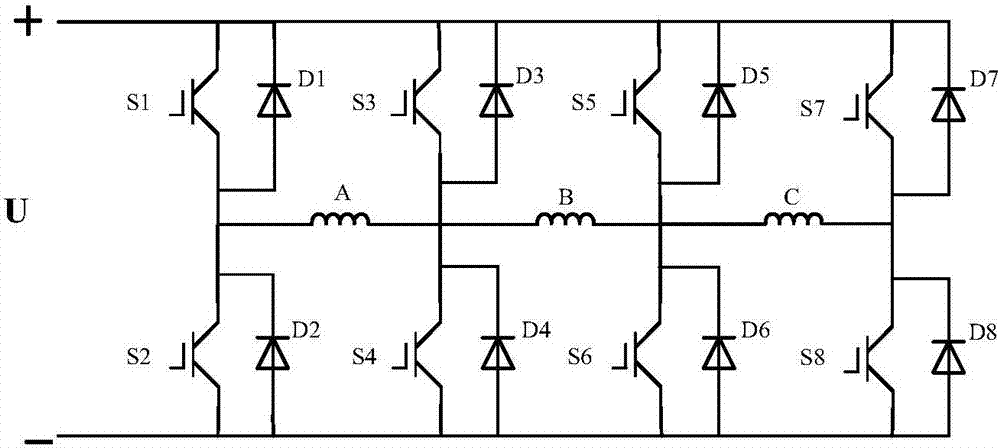
[0017] Below in conjunction with accompanying drawing, the present invention is described in further detail:

[0018] see image 3 , an external motor power conversion circuit of a permanent magnet reluctance type dual-rotor motor, including a power supply, an A-phase winding, a B-phase winding, a C-phase winding, a first bridge arm, a second bridge arm, a third bridge arm, a fourth bridge arm. The first bridge arm includes a first switch tube S1, a second switch tube S2, a first power diode D1, a second power diode D2, the first switch tube S1 is connected in series with the second switch tube S2, and the first switch tube S1 is connected in antiparallel The first power diode D1, the second switch tube S2 are antiparallel to the second power diode D2; the second bridge arm includes the third switch tube S3, the fourth switch tube S4, the third power diode D3, the fourth power diode D4, and the second bridge arm The three switching tubes S3 and the fourth switching tube S4 a...


PUM


Abstract

The invention discloses an external motor power conversion circuit of a permanent magnet reluctance type double rotor motor. The external motor power conversion circuit comprises a power supply, three-phase windings of a stator, and four parallel bridge arms. The upper end of each bridge arm is connected with a positive output end of the power supply, and the lower end is connected with a negative output end of the power supply. Each bridge arm is formed by connecting two switching tubes in series, and the two switching tubes are each connected with a power diode in parallel in the reverse direction. With regard to two adjacent bridge arms, and a phase of windings of the stator is connected in series between an emitter of the switching tube at the upper half bridge arm of one bridge arm and a collector of the switching tube at the lower half bridge arm of the other bridge arm. The external motor power conversion circuit designed for the special structure of an external motor of the permanent magnet reluctance type double rotor motor can guarantee the efficient operation of the external motor of the permanent magnet reluctance type double rotor motor, reduces the use of switching devices, improves the control performance of the external motor of the permanent magnet reluctance type double rotor motor, reduces operation cost, and promotes the application of the permanent magnet reluctance type double rotor motor.

Description

technical field [0001] The invention relates to the field of permanent magnet reluctance type double rotor motors, in particular to an external motor power conversion circuit of permanent magnet reluctance type double rotor motors. Background technique [0002] The dual-rotor motor is a new type of motor. By increasing the number of rotors, it realizes dual mechanical and dual electrical ports, and replaces the original complex electrical transmission system with one motor, which greatly simplifies the volume and quality of the transmission chain. In hybrid vehicles It has a good application prospect in wind power generation. The patent No. "CN104377921A" discloses the structure of a permanent magnet reluctance type double-rotor motor, which is the research basis of the present invention. Permanent magnet reluctance type double-rotor motor is a kind of double-rotor motor. The inner motor is a permanent magnet motor in form, which continues the advantages of high power densi...

Claims


Application Information

Patent Timeline
Patent Type & Authority Applications(China)
IPC IPC(8): H02P25/092
CPCH02P25/092
Inventor 杜锦华薛运田刘全威杨可之
Owner XI AN JIAOTONG UNIV
Why Eureka
Try Eureka