Inductive anti-leakage protector

A technology of anti-leakage and protector, which is applied in the direction of emergency protection circuit devices, automatic disconnection emergency protection devices, electrical components, etc., can solve the problems of being affected by the environment, combustible gas combustion, large leakage current, etc., and achieve the goal of eliminating short circuits Possibility, achieve close contact, and prevent the effect of heating due to virtual contact

Pending Publication Date: 2019-10-15
天津安尔诺斯科技有限公司
View PDF0 Cites 2 Cited by
  • Summary
  • Abstract
  • Description
  • Claims
  • Application Information

AI Technical Summary

Problems solved by technology

[0002] Leakage protection is a product developed to solve electric shock. Electric shock refers to the injury caused by the current passing through the human body. There are certain disadvantages in the use of existing leak-proof protectors. "Passive leakage protection technology" is to disconnect the power supply at the moment of leakage current, which has the following disadvantages. First, the leakage current is large enough to drive the actuator to disconnect the power supply. Otherwise, the leakage current is small and the power will not be cut off. , and there will be the possibility of other safety problems caused by leakage. Second, the operating voltage of the actuator is strong. The high-voltage inductive drive switch has a high probability of causing arc discharge at the moment of disconnecting the power supply, which may still cause Other combustible gases will burn, which may lead to the possibility of safety accidents. Third, due to the low sealing degree of the leakage protector, the service life cannot be guaranteed due to the influence of the environment. Once it is damaged and cannot be used, it must be inspected or replaced by a professional electrician immediately. , if the leakage protector malfunctions or refuses to operate, the reason is caused by the leakage protector itself on the one hand, and non-professionals cannot disassemble and adjust the internal components of the leakage protector without permission. protector

Method used


Image

  • Inductive anti-leakage protector
  • Inductive anti-leakage protector
  • Inductive anti-leakage protector

Examples


Embodiment Construction

[0031] In order to make the technical means, creative features, goals and effects achieved by the present invention easy to understand, the present invention will be further described below in conjunction with specific embodiments.

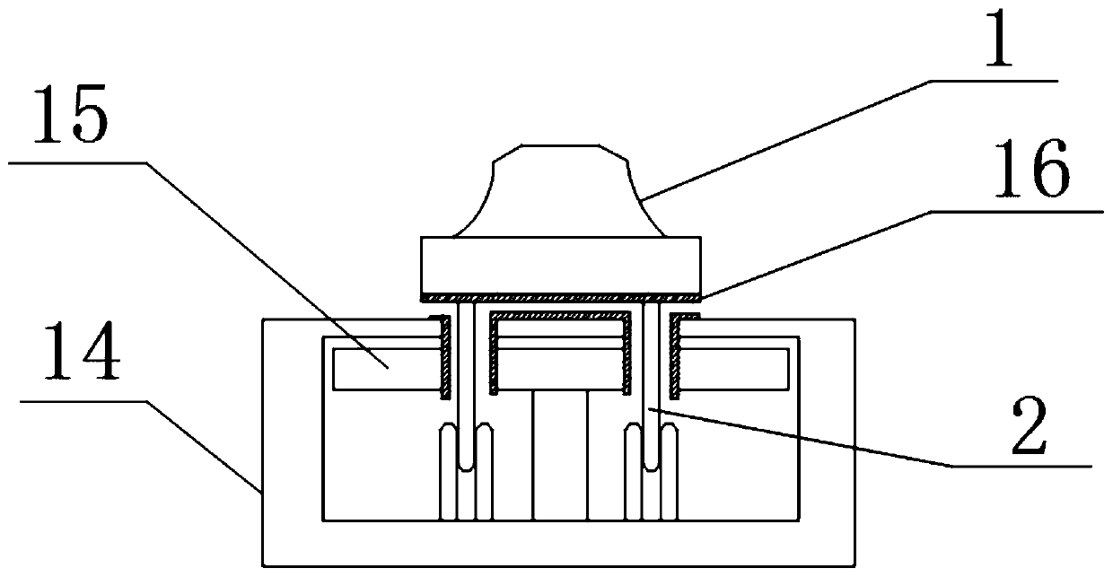
[0032] Such as Figure 1-5 As shown, an inductive anti-leakage protector includes a power supply casing 14, a limit casing 13 and an electric plug 1. Copper metal detection switch devices 15 are installed on the left and right sides of the inside of the power supply casing 14, and the copper metal detection The switch device 15 is close to the position of the copper post plug 2, and the inner end faces of the copper post plug 2 and the power supply casing 14 are provided with hydrophobic materials 16;

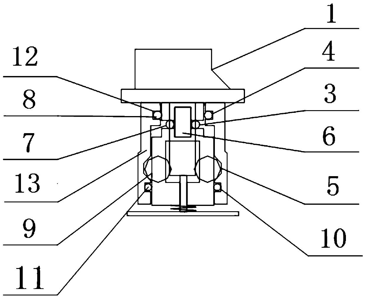
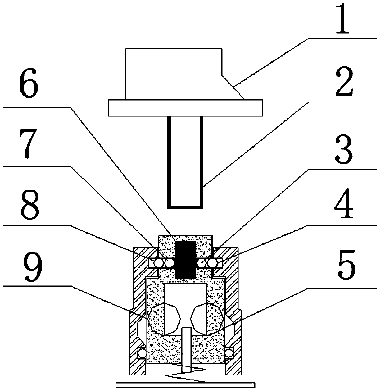
[0033] The limit inner shell 12 is installed inside the limit shell 13, and the limit inner shell 12 is embedded with a magnetic core 6, and one end of the magnetic core 6 is provided with a limit ball No. 3 limit ball 3 and a No. 4 limit ball 4 ,...


PUM


Abstract

The invention discloses an inductive anti-leakage protector, which comprises a power shell. Copper metal detection switch devices are respectively installed on the left and right sides inside the power shell. The inductive anti-leakage protector is inductively powered by a copper metal plug. Power supply starts when the copper metal plug is plugged, and no power is supplied when a plug of other size or material is plugged. Meanwhile, limit ball and lock ball structures are designed. When a copper column plug is plugged, the limit balls are locked for limiting, so as to ensure good contact of internal contacts and start power supply. Through passive leakage protection, added intelligent induction, active defense of ball limit devices and O-shaped sealing rings, the inductive anti-leakage protector can achieve an anti-leakage effect under different application conditions. By adding active defense of the intelligent anti-leakage function, high integration of the control circuit can be achieved. The power consumption of the product is low, and the product is completely packaged. Stable working conditions of a chip and a weak current part are ensured, and thus, the operation of the product can meet the requirements of various working conditions.

Description

technical field [0001] The invention belongs to the field of protectors, in particular to an inductive anti-leakage protector. Background technique [0002] Leakage protection is a product developed to solve electric shock. Electric shock refers to the injury caused by the current passing through the human body. There are certain disadvantages in the use of existing leak-proof protectors. "Passive leakage protection technology" is to disconnect the power supply at the moment of leakage current, which has the following disadvantages. First, the leakage current is large enough to drive the actuator to disconnect the power supply. Otherwise, the leakage current is small and the power will not be cut off. , and there will be the possibility of other safety problems caused by leakage. Second, the operating voltage of the actuator is strong. The high-voltage inductive drive switch has a high probability of causing arc discharge at the moment of disconnecting the power supply, whic...

Claims


Application Information

Patent Timeline
Patent Type & Authority Applications(China)
IPC IPC(8): H02H3/32
CPCH02H3/32
Inventor 田立峰
Owner 天津安尔诺斯科技有限公司
Why Eureka
Try Eureka