
Detector device

A detector and fixing technology, applied in the field of detectors, can solve the problems of inability to realize automatic control of power supply connection, cumbersome operation steps, and low safety

Inactive Publication Date: 2018-08-28
何华勇
View PDF0 Cites 0 Cited by
  • Summary
  • Abstract
  • Description
  • Claims
  • Application Information

AI Technical Summary

Problems solved by technology

[0002] Nowadays, the use of various detectors has become very popular. The current detectors are cumbersome in disassembly, inspection and maintenance, and need to be completed by disassembly work, which is not conducive to rapid disassembly, inspection and maintenance. At the same time, it is impossible to realize Automatically control the connection work of power supply, the operation steps are cumbersome and the safety is low

Method used


Image

  • Detector device
  • Detector device
  • Detector device

Examples


Embodiment Construction

[0014] Combine below Figure 1-Figure 4 The present invention will be described in detail.

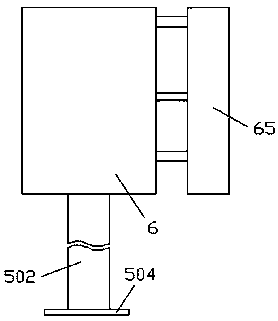
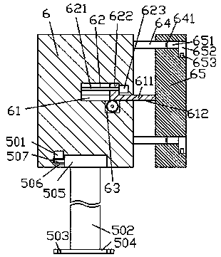
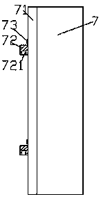
[0015] refer to Figure 1-Figure 4 , a detector device according to an embodiment of the present invention, comprising a fixing base 6 and a detector 7, a disk 505 is arranged in rotation on the bottom end surface of the fixing base 6, and the bottom end surface of the disk 505 is fixedly installed There is a vertical rod 502, the bottom end of the vertical rod 502 is fixedly installed with a backing plate 504, and the backing plate 504 is provided with a plurality of groups of holes 503 that penetrate up and down, and the holes 503 are used to pass screws through from the installation Firmly, a gear groove 506 is arranged in the inner wall body of the fixing seat 6 on the rear side of the disc 505, and a driving toothed wheel 507 is installed with a clearance fit in the gear groove 506, and the front side of the driving toothed wheel 507 end and the outer gear ring arranged in the c...


PUM


Abstract

The detector device comprises a clamping seat and a detector. A disc is rotationally arranged in the end surface of the bottom of the mounting base in a rotating mode. A vertical rod is fixedly arranged on the end surface of the bottom of the disc, and a base plate is fixedly arranged on the end surface of the bottom of the vertical rod. A plurality of sets of vertically penetrating hole cavitiesare formed in the base plate, and a gear groove is formed in the inner wall body of the fixing base on the rear side of the disc, and a driving tooth-shaped wheel is arranged in the gear groove in a clearance fit mode. The front side end of the driving tooth-shaped wheel is meshed with an outer gear ring arranged on the circumferential direction of the disc, and a motor is arranged on the top endface of the driving tooth-shaped wheel in a matched mode, and the outer surface of the motor is fixedly arranged in the inner top wall of the gear groove. A guide cavity is formed in the clamping base, and a first sliding groove extending forwards is formed in the bottom of the guide cavity, the front side extending end of the first sliding groove penetrates through the front side end face of thefixing base.

Description

technical field [0001] The invention relates to the technical field of detectors, in particular to a detector device. Background technique [0002] Nowadays, the use of various detectors has become very popular. The current detectors are cumbersome in disassembly, inspection and maintenance, and need to be completed by disassembly work, which is not conducive to rapid disassembly, inspection and maintenance. At the same time, it is impossible to realize Automatically control the connection work of the power supply, the operation steps are cumbersome, and the safety is low. Contents of the invention [0003] The object of the present invention is to provide a detector device for overcoming the above-mentioned defects in the prior art. [0004] A detector device according to the present invention, comprising a fixing base and a detector, a disk is arranged in rotation on the bottom end surface of the fixing base, a vertical rod is fixedly installed on the bottom end surface...

Claims


Application Information

Patent Timeline
IPC IPC(8): H01R13/627H01R13/70
CPCH01R13/627H01R13/701H01R2201/20
Inventor 何华勇
Owner 何华勇
Learn More