Moving-iron type electro-acoustic/acoustic-electrical conversion device

An acoustic-electric conversion, moving iron technology, applied in electrical components, sensors, etc., can solve the problems of uneven magnetic field intensity up and down the column magnet, small operating range, low efficiency, etc., and achieve good magnetic enhancement effect and high vibration sensitivity. , the effect of enhancing the coupling effect

Inactive Publication Date: 2018-08-28
WEIFANG PASADI ECONOMIC & TRADE CO LTD
View PDF0 Cites 5 Cited by
  • Summary
  • Abstract
  • Description
  • Claims
  • Application Information

AI Technical Summary

Problems solved by technology

However, the traditional electro-acoustic / acoustic-electric conversion mechanism has the problems of linear distortion and low conversion efficiency in specific operation. Taking the moving coil speaker as an example, the coil runs up and down the cylindrical magnet, and the magnetic field strength above and below the cylindrical magnet is uneven. Yes, only the middle part is relatively uniform, the operating range in the uniform magnetic field is small, and the signal line with large amplitude begins to leave this area, causing the magnetic field where the coil is located to gradually weaken, the Lorentz force on the coil decreases, and the force that pushes the paper cone to move The force is not proportional to the amplitude of the input audio signal, which is equivalent to compressing the amplitude of the peak, resulting in distortion
The planar speaker uses the principle of isomagnetism. It uses planar magnets in its cavity. The magnetic force lines of the planar magnets are distributed in a ring. The ring-shaped magnetic force lines are coupled with the planar coils. The interaction is poor, the efficiency is very low, and it is difficult to drive. It can only be achieved by enlarging the magnet. The method of area is solved, the increase of the magnet will increase the weight of the product, which also increases the wearing pressure

Method used


Image

  • Moving-iron type electro-acoustic/acoustic-electrical conversion device
  • Moving-iron type electro-acoustic/acoustic-electrical conversion device
  • Moving-iron type electro-acoustic/acoustic-electrical conversion device

Examples


Embodiment Construction

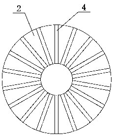
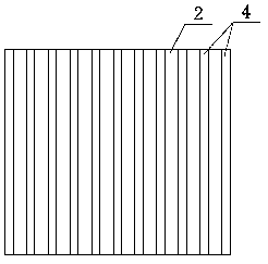
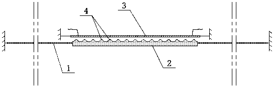
[0024] With reference to accompanying drawing, moving iron type electro-acoustic / acoustic-electric conversion device of the present invention comprises permanent magnet part, coil part and diaphragm 1, and permanent magnet part is planar magnet 2, and coil part comprises coil substrate 3 and is built in coil substrate In the coil winding, the planar magnet 2 and the diaphragm 1 are connected as an integral structure, the coil substrate 3 and the planar magnet 2 are arranged in parallel, and a plurality of convex ribs 4 are arranged at intervals on the plane corresponding to the planar magnet 2 and the coil substrate 3, and each convex The ribs 4 are arranged in parallel on the surface of the planar magnet 2 or spaced rings are arranged on the circumference of the surface of the planar magnet 2 .

[0025] Wherein, planar magnet 2 can be circular, oval or square, when planar magnet 2 is circular or oval, as figure 1 As shown, the ribs 4 spaced rings are arranged on the circumfer...


PUM


Abstract

The invention relates to a moving-iron type electro-acoustic / acoustic-electrical conversion device. The conversion device comprises a permanent magnet part, a coil part and a vibrating diaphragm; thestructural feature is that the permanent magnet part is the plane magnet, the coil part comprises a coil substrate and a coil winding built in the coil substrate; the plane magnet and the vibrating diaphragm are connected as an integer structure; the coil substrate and the plane magnet are arranged in parallel; multiple ribs are arranged on the corresponding planes of the plane magnet and the coilsubstrate at intervals; various ribs are arranged on the surface of the plane magnet in parallel or distributed on the circumference location of the plane magnet surface at intervals. The conversiondevice has the advantages of being simple in structure, convenient for realization, small in linear distortion and high in conversion efficiency.

Description

technical field [0001] The invention relates to a moving iron type electro-acoustic / acoustic-electric conversion device. Background technique [0002] The speaker is an electro-acoustic conversion product. For a dynamic speaker, its working principle is: the coil (voice coil) of the speaker is connected to an AC audio current, and an alternating magnetic field is generated around the coil. Since the coil is located in the speaker's own In the magnetic field of the permanent magnet, therefore, the two magnetic fields generate an interaction force, causing the coil to vibrate with the amplitude of the audio current. In the speaker, the coil and the diaphragm are integrated, and the diaphragm follows the vibration of the coil to produce sound, thereby completing the electrical signal to the machine. Vibration conversion. [0003] A microphone is a sound-to-electricity conversion product. Taking a dynamic microphone as an example, its working principle is just the opposite of t...

Claims


Application Information

Patent Timeline
Patent Type & Authority Applications(China)
IPC IPC(8): H04R9/04H04R9/02
CPCH04R9/025H04R9/04
Inventor 李翰林
Owner WEIFANG PASADI ECONOMIC & TRADE CO LTD
Why Eureka
Try Eureka