Winding device with base for vertical pouring

A winding and base technology, applied in the direction of transformer/inductor coil/winding/connection, transformer/inductor components, coil manufacturing, etc., to avoid crack formation and simplify preparation.

Inactive Publication Date: 2021-04-02
SIEMENS AG
View PDF6 Cites 0 Cited by
  • Summary
  • Abstract
  • Description
  • Claims
  • Application Information

AI Technical Summary

Problems solved by technology

[0005] The known winding arrangement and the known method have the disadvantage that the winding arrangement can only be erected, in other words in a vertical position, only after the winding insulation has hardened

Method used


Image

  • Winding device with base for vertical pouring
  • Winding device with base for vertical pouring
  • Winding device with base for vertical pouring

Examples


Embodiment Construction

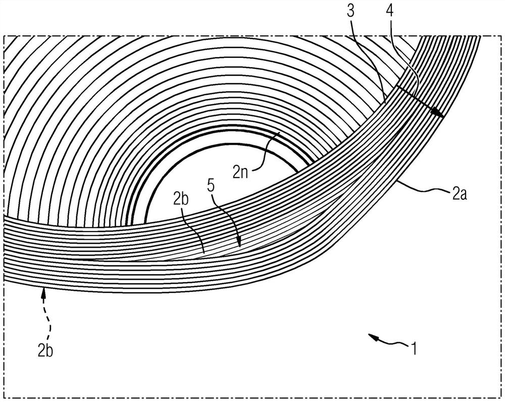
[0034] figure 1An exemplary embodiment of the winding arrangement 1 according to the invention is shown in a perspective view from below. It can be seen that the winding arrangement 1 has a plurality of disk windings 2 , 2 b , 2 c . It can be seen that the disk winding 2a and also all the other disk windings 2b...2n are assembled from a plurality of winding layers 3 with strip-shaped, ie flat, conductors which are rolled from the inside to the outside. Winding, wherein each disc winding 2a, 2b, 2c, . . . 2n increases in radial direction 4. Here, the strip-shaped conductors are insulated from one another. The insulation part is in figure 1 The illustrated embodiment is provided by a layer of paint that has been applied to the conductor. Depend on figure 1 It can be seen in particular that the disc winding 2 a forms a recess 5 which is provided for receiving a fixed end of the base element.

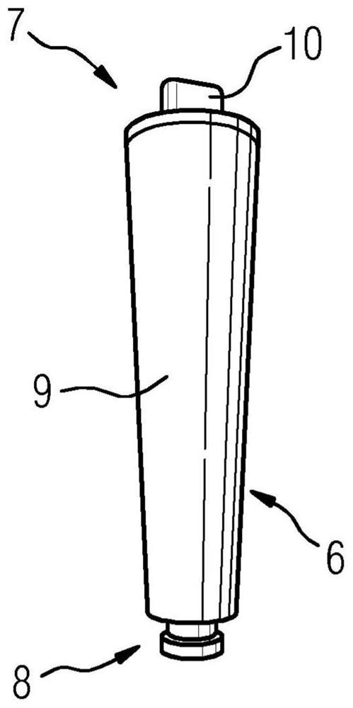
[0035] figure 2 An embodiment of a base element 6 is shown, which has a fixed e...


PUM

PropertyMeasurementUnit
Thicknessaaaaaaaaaa

Abstract

In order to provide a winding arrangement (1) with a plurality of winding segments (2a, 2b, . Arranged at a distance and electrically connected to each other so as to form a series circuit, the winding arrangement enables vertical casting with winding insulating material, at least one base element (6) is provided, which is connected to the winding segment (2a) And it is arranged to carry the entire winding device (1).

Description

technical field [0001] The invention relates to a winding arrangement with a plurality of winding segments arranged one above the other in the vertical direction, which are arranged at a distance from one another and are electrically connected to each other to form a series circuit. [0002] Furthermore, the invention relates to a method for producing a winding arrangement. Background technique [0003] Such winding arrangements and such methods are known from long-standing practice. Then, for example, a winding arrangement is shown on page 5 under the number E5001-G640-A143-V2 in the catalog given by Siemens AG in 2014, which is used as a high-voltage winding in the field of energy distribution for dry in the transformer. The winding arrangement shown therein has disk windings as winding segments which are arranged at a distance from one another and are completely embedded in the winding insulator. The winding insulator has a molded casting base, which is provided at its...

Claims


Application Information

Patent Timeline
IPC IPC(8): H01F41/12H01F27/32
CPCH01F27/322H01F27/324H01F27/327H01F41/122H01F41/125H01F41/127H01F27/323H01F27/32H01F41/12
Inventor R.希莱T-F.梅S.韦纳特
Owner SIEMENS AG
Why Eureka
Try Eureka