
Forklift

A technology for forklifts and frames, applied in the field of lifting equipment, can solve the problems of different weights, low work efficiency, and high costs, and achieve the effects of ensuring normal use, low manufacturing costs, and wide application scope.

Active Publication Date: 2018-08-31
青岛中检检验有限公司
View PDF6 Cites 3 Cited by
  • Summary
  • Abstract
  • Description
  • Claims
  • Application Information

AI Technical Summary

Problems solved by technology

[0003] There are many types of forklifts at present, which are generally large in size and complex in structure, and the efficiency of maintenance when the forklift fails is low; Manual handling is time-consuming and labor-intensive, and the work efficiency is low; when moving goods, if some goods have different weights due to substandard quality, ordinary forklifts cannot distinguish such goods; so there is no A forklift that can easily lift goods, is easy to overhaul, and can distinguish substandard goods

Method used


Image

  • Forklift
  • Forklift

Examples


Embodiment 1

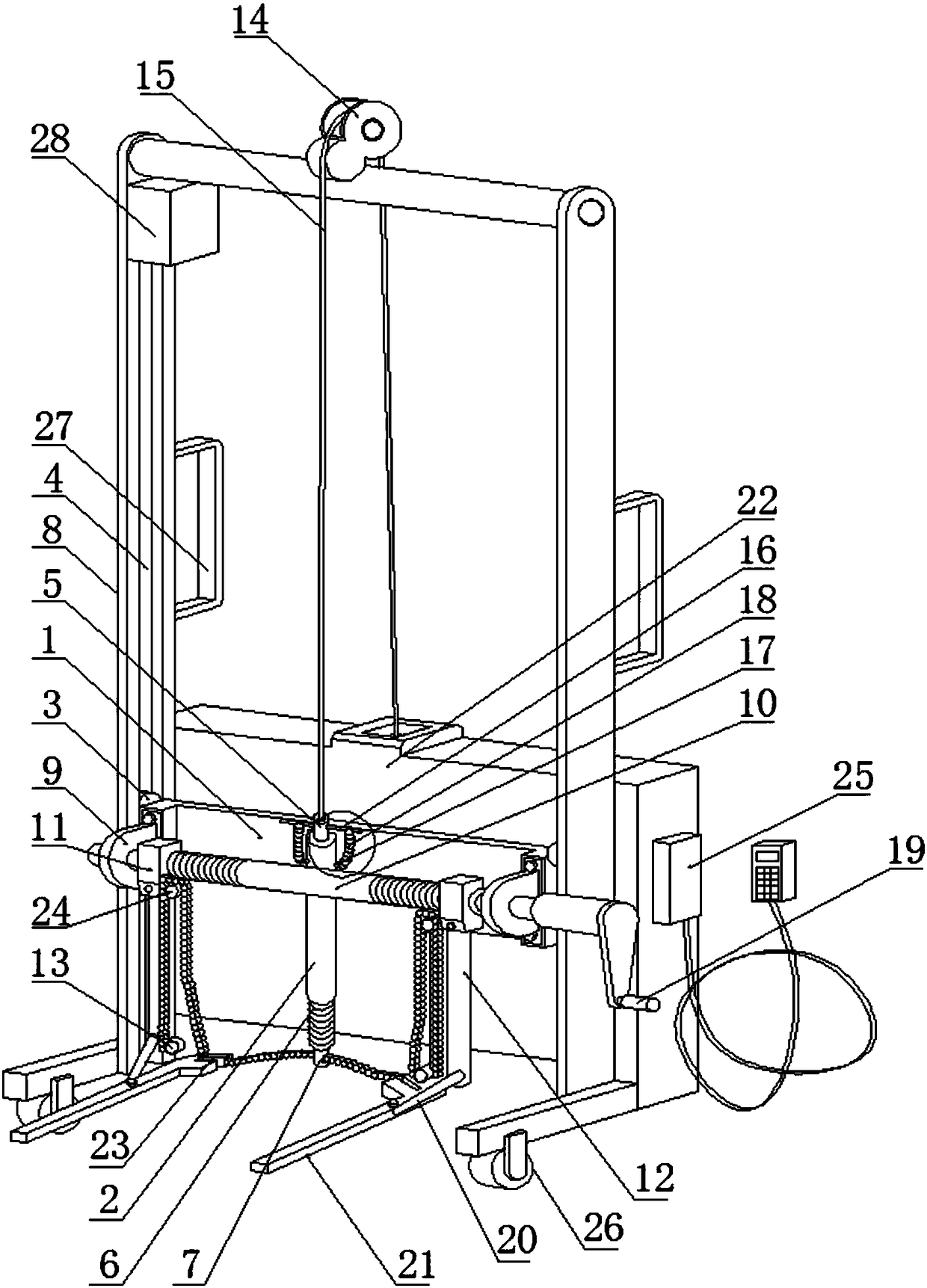
[0022] Embodiment 1, with reference to figure 1 —2, a kind of forklift, comprises warehouse body, and described forklift comprises vehicle frame 8;

[0023] The vehicle frame 8 is provided with a lifting mechanism, and the lifting mechanism includes a lifting plate 1, a lifting bushing 2 fixed on the lifting plate 1 and a lifting shaft 5 arranged in the lifting bushing 2; Both sides of the board 1 are provided with slide blocks 3, and the frame 8 on both sides of the lifting board 1 is provided with slide rails 4 used in conjunction with the aforementioned slide blocks 3; the bottom end of the lifting shaft sleeve 2 and the bottom end of the lifting shaft 5 are An elastic element 6 is connected between them, and a through hole 7 is also provided at the bottom end of the lifting shaft 5;

[0024] The vehicle frame 8 is also provided with a clamping mechanism, and the clamping mechanism includes two supports 9 fixed on the lifting plate 1, a rotating shaft 10 pierced on the two...

Embodiment 2

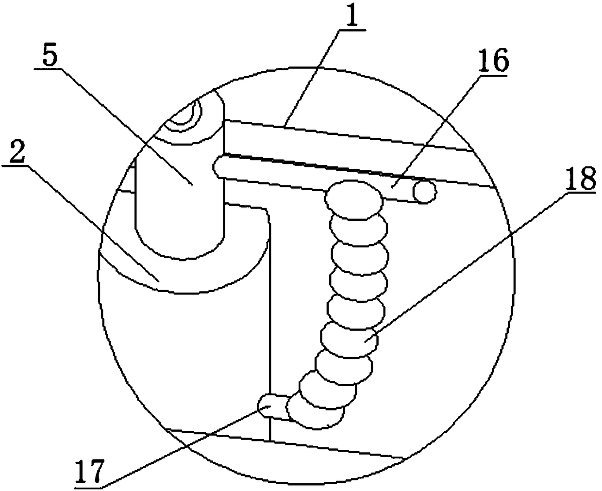
[0026] Embodiment 2, a kind of forklift described in embodiment 1, described lifting mechanism is also provided with auxiliary lifting mechanism, and described auxiliary lifting mechanism comprises the connecting shaft 16 that crosses on aforementioned lifting shaft 5, is arranged on The extension spring mounts 17 on both sides of the lifting bushing 2 and the extension spring 18 connected between the connecting shaft 16 and the extension spring mounts 17 .

Embodiment 3

[0027] Embodiment 3, a kind of forklift described in Embodiment 1, the distance adjustment mechanism is also provided on the described clamping mechanism, and the distance adjustment mechanism includes the aforementioned rotating shaft 10, the rotating arm mounting seat 11 and the The handle 19 at the end; the shaft 10 is tapped with thread; the rotating arm mounting seat 11 is provided with a thread used in conjunction with it.


PUM


Abstract

The invention provides a forklift. The forklift comprises a forklift frame. The forklift frame is provided with a lifting mechanism. The lifting mechanism comprises a lifting plate, a lifting shaft sleeve fixed to the lifting plate, and a lifting shaft arranged in the lifting shaft sleeve. Sliding blocks are arranged on the two sides of the lifting plate. Sliding rails used in cooperation with thesliding bocks are arranged on the portions, on the two sides of the lifting plate, of the forklift frame. An elastic element is connected between the bottom end of the lifting shaft sleeve and the bottom end of the lifting shaft. A through hole is formed in the bottom end of the lifting shaft. The forklift frame is further provided with a clamping mechanism. The clamping mechanism comprises two supports fixed to the lifting plate, a rotary shaft arranged on the two supports in a penetrating mode, and two rotary arm installation bases arranged on the rotary shaft. Rotary arms are rotatably connected to the two rotary arm installation bases separately. Positioning columns are also arranged on the two rotary arm installation bases. Clamping arms are rotatably connected to the ends of the rotary arms. The forklift is low in manufacturing cost, wide in application range and high in work efficiency.

Description

technical field [0001] The invention relates to the field of lifting equipment, in particular to a forklift. Background technique [0002] Forklift is an industrial handling vehicle, which refers to various wheeled handling vehicles for loading and unloading, stacking and short-distance transportation of finished goods, and plays an important role in moving goods. [0003] There are many types of forklifts at present, which are generally large in size and complex in structure, and the efficiency of maintenance when the forklift fails is low; Manual handling is time-consuming and labor-intensive, and the work efficiency is low; when moving goods, if some goods have different weights due to substandard quality, ordinary forklifts cannot distinguish such goods; so there is no A forklift that can easily lift goods, is easy to overhaul, and can distinguish substandard goods. Contents of the invention [0004] The technical problem to be solved by the present invention is to p...

Claims


Application Information

Patent Timeline
Patent Type & Authority Applications(China)
IPC IPC(8): B66F9/18B66F9/20
CPCB66F9/18B66F9/205B66F2700/09Y02T10/70
Inventor 孙钦法
Owner 青岛中检检验有限公司
Learn More