

Heavy anti-vibration pipe clamp
An anti-vibration pipe and pipe clamp technology, applied in the direction of pipe supports, pipes/pipe joints/pipes, mechanical equipment, etc., can solve the problems of pipe fatigue, pipe mixing vibration, easy to cause accidents, etc., to improve the stability and prolong the use. Longevity and effect of improving anti-vibration performance
- Summary
- Abstract
- Description
- Claims
- Application Information
AI Technical Summary
Problems solved by technology
Method used
Image

Examples
Embodiment 1
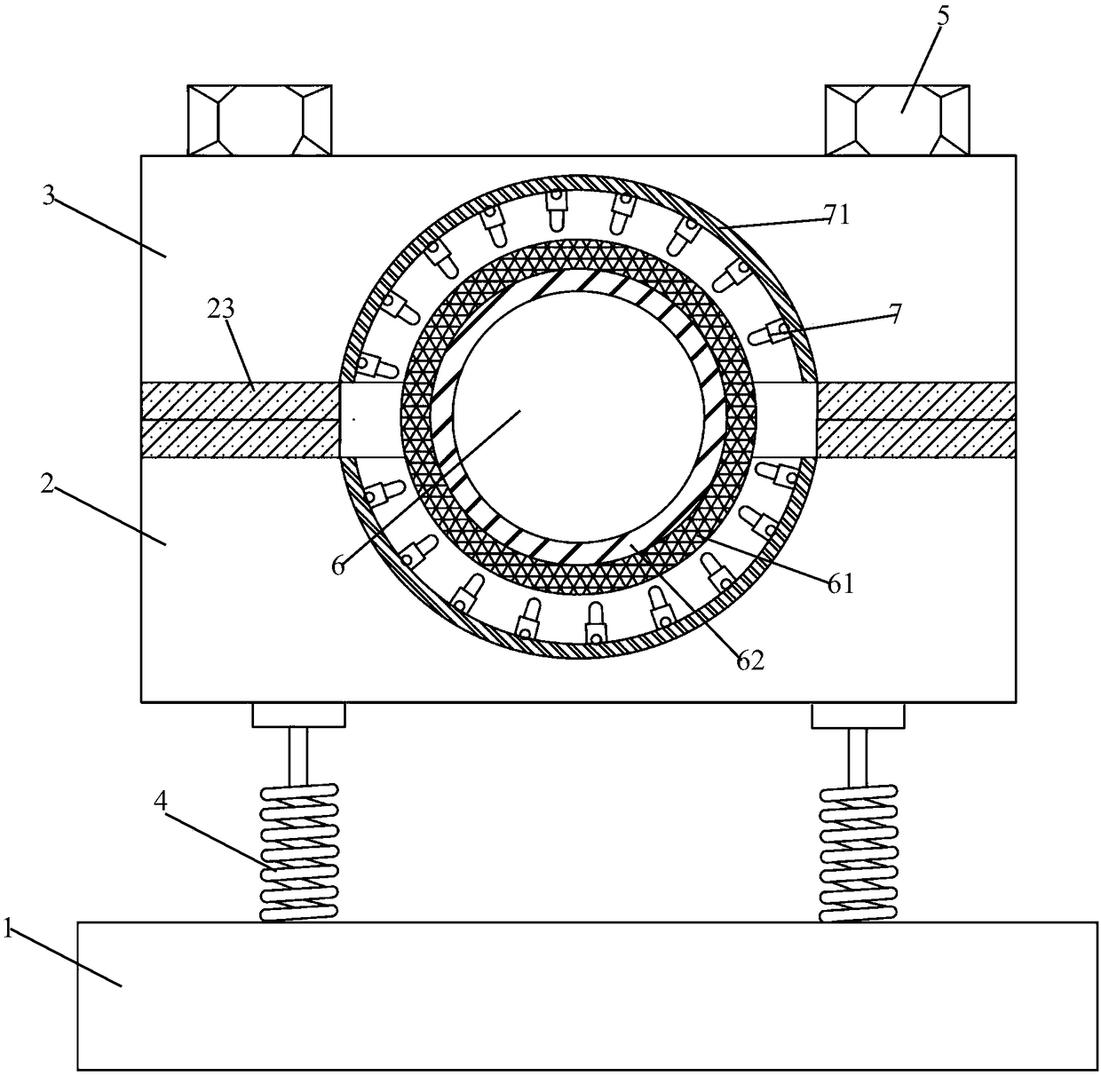
[0035] Embodiment 1: A heavy-duty shock-proof pipe clamp disclosed in the embodiment of the present invention includes a base 1, a lower pipe clamp 2 and an upper pipe clamp 3 sequentially connected to the base 1, and the base 1 is evenly connected to the base 1 through a plurality of shock absorbers 4. The bottom end of the lower pipe clamp body 2 is connected, the lower pipe clamp body 2 and the upper pipe clamp body 3 are connected by bolts 5, and a pipe clamp hole 6 is formed, and an anti-vibration device is arranged on the inner wall of the pipe clamp hole 6, and the anti-vibration device includes The rubber ring 61 connected with the inner wall of the pipe clamp hole 6 and the shockproof plate 62 connected with the rubber ring 61, one side of the rubber ring 61 is provided with threads, and is threaded with the inner wall of the pipe clamp hole 6, and the other side is provided with a groove, and A bump is provided in the groove, and the anti-vibration plate 62 is matched...
Embodiment 2
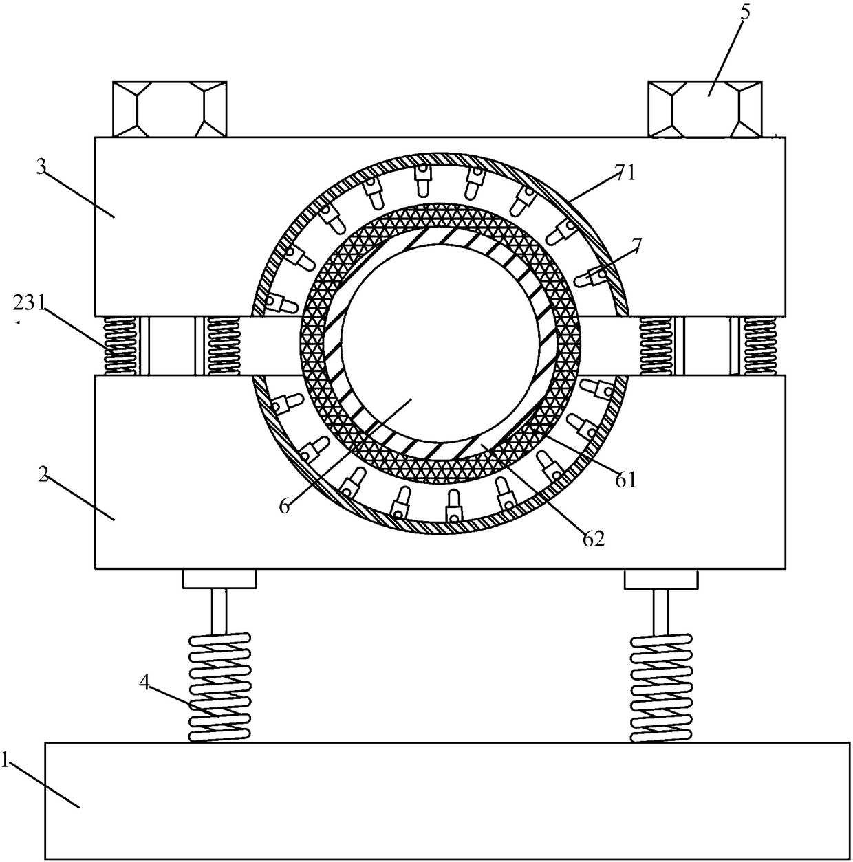
[0036]Embodiment 2: A heavy-duty shockproof pipe clamp disclosed in the embodiment of the present invention includes a base 1, a lower pipe clamp body 2 and an upper pipe clamp body 3 sequentially connected to the base 1, and the base 1 is uniformly connected to the base 1 through a plurality of shock absorbers 4. The bottom of the lower pipe clamp body 2 is connected, the lower pipe clamp body 2 and the upper pipe clamp body 3 are connected by bolts 5, and a pipe clamp hole 6 is formed, and an anti-vibration device is arranged on the inner wall of the pipe clamp hole 6, and the anti-vibration device includes The rubber ring 61 connected with the inner wall of the pipe clamp hole 6 and the shockproof plate 62 connected with the rubber ring 61, one side of the rubber ring 61 is provided with threads, and is threaded with the inner wall of the pipe clamp hole 6, and the other side is provided with a groove, and A bump is provided in the groove, and the anti-vibration plate 62 is ...
PUM
 Abstract
Description
Claims
Application Information