

Flexible direct current transmission suspended type valve tower, assembly method and suspension connection structure thereof
A flexible DC power transmission and connection structure technology, applied in the direction of DC network circuit devices, circuit devices, electrical components, etc., can solve the problems of no maintenance channel, weak seismic strength, difficult on-site installation, etc., to improve work efficiency, convenience and speed. Assembly, the effect of increased shock resistance
- Summary
- Abstract
- Description
- Claims
- Application Information
AI Technical Summary
Problems solved by technology
Method used
Image

Examples
Embodiment Construction
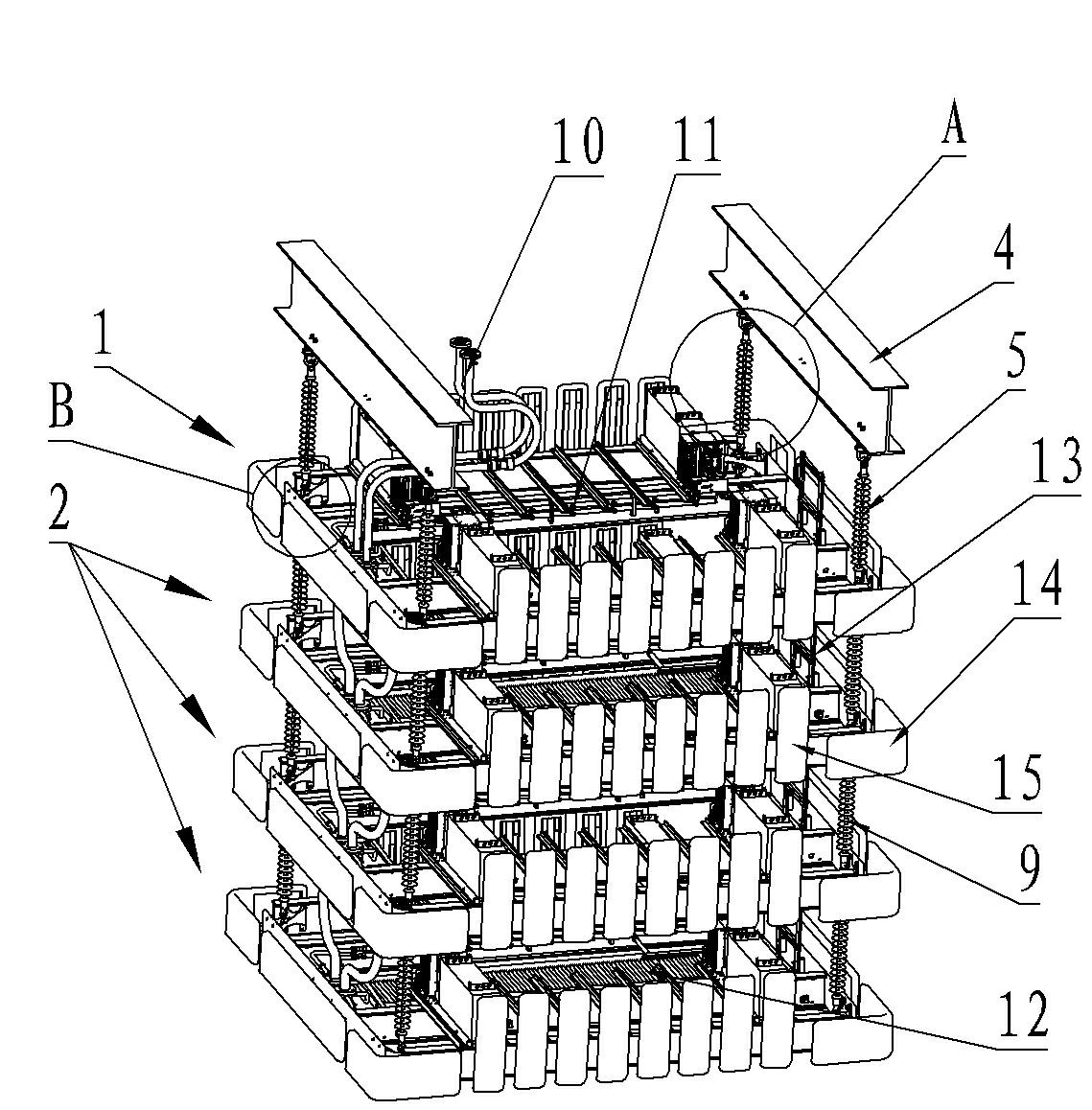
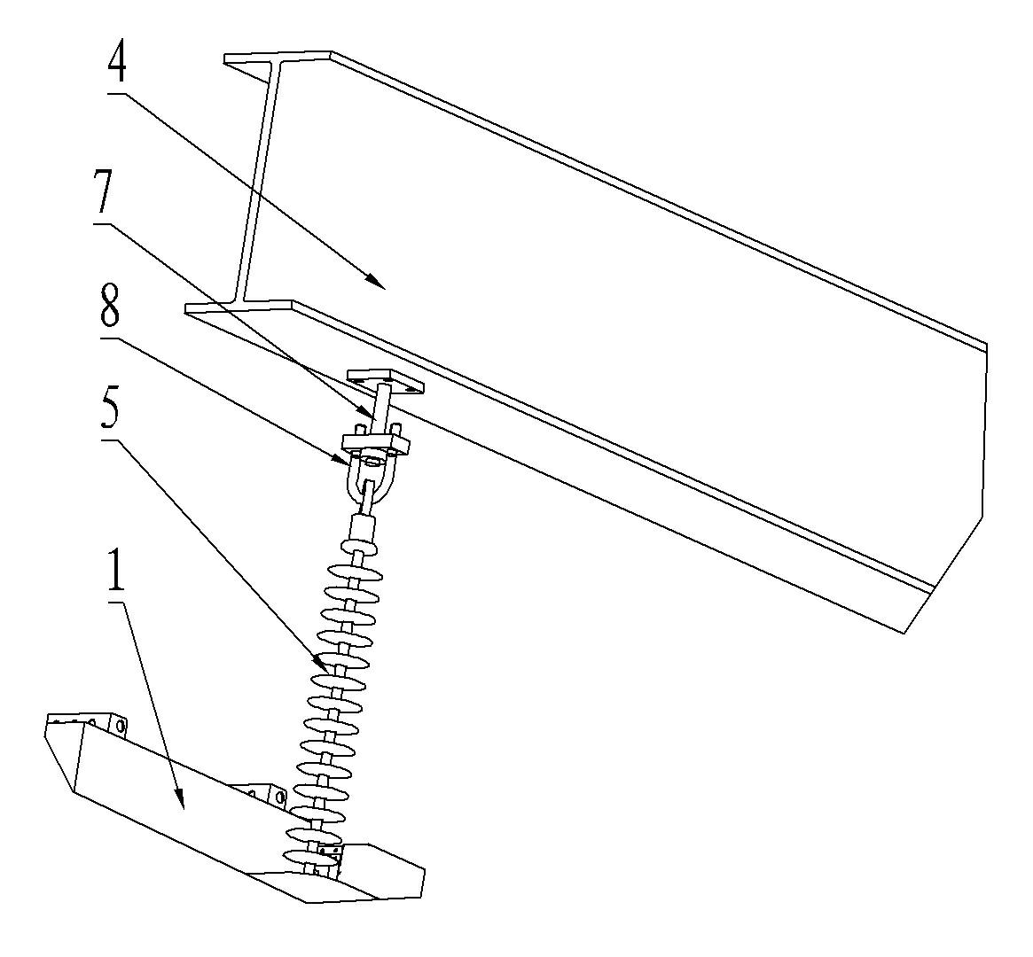
[0023] Embodiment of the assembly method of the flexible DC transmission suspension valve tower of the present invention: the assembly method includes the following steps: the first step is to hang the top floor valve group under the steel beam of the building through the suspension connection structure, and the The suspension connection structure includes an insulator, a U-bolt fastened at one end of the insulator, and a splayed ring hinged at the other end of the insulator; in the second step, each lower valve group is sequentially connected under the top valve group through the above-mentioned suspension connection structure. Suspended below the top valve block.
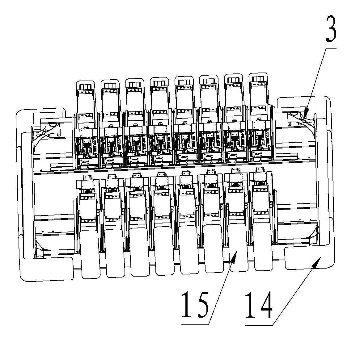
[0024] Embodiments of the flexible DC transmission suspension valve tower of the present invention: as Figure 1 to Figure 4 As shown, the valve tower includes a top valve group 1 and three lower valve groups 2. Both the top valve group 1 and the lower valve group 2 have four connection angles 3 at their four corn...
PUM
 Abstract
Description
Claims
Application Information