Smart pet ring, and pet monitoring system and monitoring method
A monitoring system and pet technology, applied in the field of smart pet rings, can solve the problems of pet loss, not being well resolved, lack of pet intelligent monitoring, etc., and achieve the effect of complete functions and easy implementation
Inactive Publication Date: 2018-08-31
CENTRAL SOUTH UNIVERSITY OF FORESTRY AND TECHNOLOGY
10 Cites 4 Cited by
AI-Extracted Technical Summary
Problems solved by technology
At present, there is a lack of products and systems for intelligent monitoring of pets on the market, which cannot meet consumers' needs for monitoring pets at all.
Moreover, problems such a...
Method used
(1) Heart rate detection of pet: There are also many measuring methods and sensors for heart rate. You can use the MAX30102 heart rate sensor. The MAX30102 is an integrated pulse oximeter and heart rate monitor biosensor module with low power consumption and space savings. It integrates a red LED and an infrared LED, a photodetector, an optical device, and low-noise electronics with ambient light suppression. MAX30102 uses a 1.8V power supply and an independent 5.0V power supply for internal LEDs. In addition, the chip can also shut down the module through software, and the standby current is close to zero, so that the power supply can always maintain...
Abstract
The invention discloses a smart pet ring, and a pet monitoring system and monitoring method. The smart pet ring comprises a ring body, a main control module, a power source module, a positioning module, a communication module and a detecting module, wherein the main control module, the power source module, the positioning module, the communication module and the detecting module are arranged at the ring body. The power source module, the positioning module, the communication module, and the detecting module are connected with the main control module. The main control module being an Android main control module is used for processing data. The power source module is used for providing power for the main control module, the positioning module, the communication module and the detecting module. The positioning module is used for acquiring positioning data. The communication module is used for carrying out wireless communication and emergency communication between the ring body and a cloudserver. The detecting module is used for detecting body signs of a pet. According to the invention, the smart pet ring, and the pet monitoring system and monitoring method are easy to implement; theposition and vital signs of the pet can be monitored in real time; and the smart pet ring can be combined with the mobile phone APP, so that the functions are perfected.
Application Domain
Programme controlComputer control +1
Technology Topic
Mobile phoneMonitoring system +3
Image
Examples
- Experimental program(2)
Example Embodiment
[0057] Embodiment 1: In view of the loss of pets, the occurrence of emergencies, and the continuous improvement of consumers' requirements for breeding, relevant coping technologies are proposed. The specific functions of the smart pet ring include:
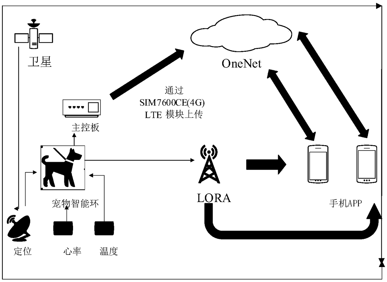
[0058] ①: Intelligent positioning of pets: Consumers can use this function to accurately locate pets anytime and anywhere. It can not only prevent pets from being lost, but also find them conveniently.
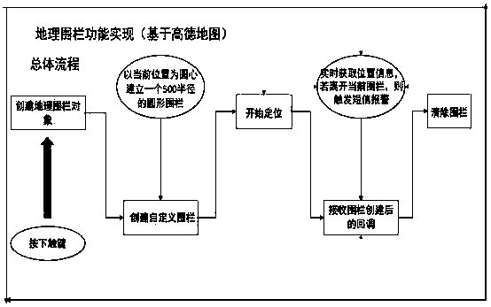
[0059] ②: Electronic fence: Consumers can use this function to set the maximum range of activities for pets. If the pet's activities exceed the range, an alarm will be sent to the consumer. If the location mode is not turned on, the location will be automatically turned on.
[0060] ③: Information matching: It is equivalent to the exclusive certificate of pets. Part of the information and contact information of consumers (pet owners) and related information of pets can be obtained by scanning the QR code.
[0061] ④: Real-time detection of physical signs: Consumers can check the pet's heart rate and temperature indicators in real time to judge the pet's physical health.
[0062] ⑤: Emergency alarm: Through the analysis and judgment of pet heart rate, temperature and other indicators, if the pet encounters an emergency, it will automatically trigger an alarm to remind consumers.
[0063]⑥: Cloud data sharing: A social platform dedicated to pets, where consumers can post text, photos, videos, etc. in the APP to communicate with other consumers. To upload photos and videos to the cloud for storage.
[0064] In order to realize and operate the project functions stably, the system has three levels:
[0065] a. Detection perception layer:
[0066] The hardware part of the project mainly includes MAX30102 heart rate sensor, MLX90614ESF non-contact-infrared temperature sensor, GPS/Beidou module, Android main control system and LORA communication device. Among them, the Android main control system includes the main control board, LTE (SIM7600CE) communication module, sensor part, and collects relevant data in real time. LORA communication module hardware mainly includes Android TPLORA main control board, GPS/BD2 module and DX-BT05-A4.0 Bluetooth module.
[0067] b. Transport layer:
[0068] After the detection perception layer collects data, it is sent to the Android main control system. The LTE (SIM7600CE) communication module is responsible for sending the data collected by the Android main control board to the cloud through the LTE (4G) network. The cloud stores the processed data and can be viewed through the mobile phone APP. The LORA module is an emergency communication part, which can transmit emergency alarm signals to consumers in a timely manner when the network is not smooth.
[0069] c. Terminal application layer:
[0070] Design an APP on the mobile terminal, you can view the data collected and analyzed by the sensor, you can receive alarm signals, you can post news in the "pet circle", and communicate and share with other consumers.
[0071] Overall plan:
[0072] The overall structure of the system includes ATGM332D positioning module, heart rate detection module, temperature infrared detection module, main control board, LTE (SIM7600CE) communication module, LORA communication module, cloud, mobile APP. The main control board is responsible for receiving instructions from users and data collected by bottom sensors and realizing corresponding control functions. The LTE (SIM7600CE) communication module is responsible for uploading the collected data to the OneNet cloud platform, and the mobile APP obtains the data on the cloud platform. The LORA module is the emergency communication part, which mainly realizes emergency communication when the mobile communication network is not smooth and the signal is not good. The overall planning structure diagram is as follows figure 1 shown.
[0073] 1 pet positioning:
[0074] The hardware part of the smart pet ring positioning system integrates LTE (SIM7600CE) module and GPS/BD2 module, and the accuracy of the positioning system can be improved through the dual-mode positioning mode. Beidou positioning itself can improve the communication capabilities of the positioning system. The location information obtained by the GPS/BD2 module is uploaded to the Onenet cloud platform through the LTE (4G) network, and the data of the Onenet cloud platform is reflected in the app, and the user can obtain the real-time location of the pet through the APP.
[0075] The APP part of the software is written on the basis of the Onenet cloud platform, and the Amap is integrated inside. After obtaining the location data, it can be directly displayed on the Amap. See figure 2.
[0076] 2 Real-time detection of physical signs:
[0077] like image 3 , heart rate, temperature detection:
[0078] The smart pet ring has the function of detecting the heart rate of pets. The real-time heart rate of the pet is detected by the sensor, and the data is uploaded to the cloud. Consumers can check it in the APP and pay attention to the physical condition of the pet at any time.
[0079] Health status
[0080] In addition to the real-time observation of pet physical signs data, the smart pet ring can also compare with the normal data range under health conditions to obtain the pet's physical health. Can be divided into three situations: healthy; sub-health; sick. For example, the heart rate of a general medium-sized dog is about 90 beats per minute (different breeds will have subtle differences), the larger the dog breed, the lower the heart rate, and vice versa, the higher the heart rate; usually the normal body temperature of a dog is between 37.7 and 39.2 between degrees Celsius. (Other pets also have normal index ranges) If the heart rate and temperature detection indexes of pet dogs of the same breed are within the normal range, it is in a healthy state; if one or both indexes are near the normal range and do not change suddenly and remain for a certain period of time, then it is Sub-health state; if one or both indexes deviate from the normal range more and do not change suddenly and remain for a certain period of time, it is a sick state. Through mastering the physical indicators of pets, consumers can consult senior veterinarian pet experts on the APP social platform according to the abnormal conditions of the indicators, or go to the pet hospital for examination to avoid further deterioration of the physical condition. Guarantee the detection of the health of pets at any time, so that the pets can reach the best feeding status.
[0081] 3 Safety precautions:
[0082] (1) Electric fence
[0083] The electronic fence is an expansion function based on pet positioning, which is mainly realized by software technology. The appropriate range can be set by the user in the APP. When doing outdoor activities, turn on this function and set up a safe range of electronic fences. If the pet exceeds the range, an alarm will appear on the APP.
[0084] (2) Emergencies
[0085] Through the continuous real-time collection of pet physical signs data, we can not only judge the physical health of pets, but also judge the occurrence of emergencies. According to the relevant knowledge of animal physiology and veterinary clinical diagnosis, when pets are in a healthy state, their body temperature and heart rate will be maintained within a certain range in a normal environment. Maintain at 90-160 beats/min, at this time you can record and calculate the average heart rate (different species and different body types vary). When the rhythm is disturbed, for example, the heart rate of a dog can be as high as 360 beats/min and as low as 50 beats/min. When similar sharp changes occur in real-time data, the sudden increase or decrease of heart rate and temperature exceeds a certain range of data under normal circumstances previously counted (body temperature changes exceed plus or minus 4 degrees Celsius within 1 minute, heart rate changes exceed the normal average heart rate) When it lasts for 1-2 minutes or there is still a tendency to change to an abnormal direction, it can be judged that the pet is in an abnormal environment. If this happens, an alarm prompt will also appear in the APP.
[0086] (3) Information matching
[0087] This function is based on the information input and storage of the QR code. Consumers fill in relevant information in the APP in advance, including contact information, pet breed, age, gender and other basic information. It can be viewed by scanning the QR code. According to the entered information, the physical signs and indicators of pets of different breeds, ages and genders can be searched in the information database, so as to make a more accurate judgment on the physical condition of pets. It is also convenient to contact the user when the pet is lost.
[0088] (4) LORA communication
[0089] When the network is not smooth, the GPS module on the LORA portable device carried by the pet ring will obtain GPS data, and after analysis, the GPS data will be sent to consumers through LORA communication technology, and uploaded to the APP through Bluetooth. In the absence of GSM and other networks Realize the positioning of pets under certain conditions and improve the reliability of communication.
[0090] For details, see Figure 4.
[0091] Terminal functions: see Figure 5 , including the following sections:
[0092] (1) Consumers can view the real-time data of the pet's heart rate and temperature collected by the sensor and the health status after data analysis on the APP.
[0093] (2) The effective range of the electronic fence can be set on the APP.
[0094] (3) The APP integrates the Gaode map, which can display the current location of the pet on the map.
[0095] (4) When an emergency occurs, the APP can receive an alarm signal.
[0096] (5) The APP can store the information entered by consumers, and also store the data collected by sensors and positioning modules, so that consumers can view it later. According to the input pet information, it can be matched with the database to find out the normal physical sign data of the pet type, and can also provide some correct feeding methods for specific pet types.
[0097] (6) The APP is written on the basis of the Onenet cloud platform, and the data of each project function is uploaded to the cloud platform, which can be directly detected and viewed in real time in the APP. Users can upload videos and photos about pets to the cloud for storage, and can also communicate and share with other users to build a social platform dedicated to pets.
[0098] hardware composition
[0099] 1 hardware architecture
[0100] Referring to Figure 6, the hardware part of the smart pet ring includes the ANDROID main control system and the LORA communication device, as well as the underlying GPS/BD2 positioning module, heart rate detection module and temperature detection module.
[0101] 2ANDROID main control board
[0102] The main control board adopts ANDROID MEGA2560. ANDROID MEGA2560 is a microcontroller development board with ATmega2560 as the core. It has 54 sets of digital I/O terminals (15 of which can be used as PWM output), 16 sets of PWM input terminals, 4 sets of UART, and 16MHz imported crystal oscillator. Its working voltage is 5V, and the range of input voltage is 6-20V. The Mega 2560 has 256K of flash memory.
[0103] 3 communication system
[0104] 3.1 SIM7600CE
[0105] The SIM7600CE module is a communication development module that supports LTE (4G) full Netcom, and also supports 3G (EV_DO/HSPA+), 3G (WCDMA), 2.5G (EDGE), and 2G (GSM/GPRS) communications. Support LTECAT4 (downlink speed is 150Mbps), support USB communication power supply, optional MIFI/WIFI module, adopt NANO-SIM card flip cover card slot, support voice function, board TF card slot. External 5V power supply. The onboard lithium battery charging circuit can be connected to 3.7V-4.2V lithium battery. The performance is stable, and the transmission of SMS and data information can be realized with low power consumption.
[0106] 3.2LORA communication module
[0107] like Figure 7 , LORA communication module hardware mainly includes ANDROID TPLORA main control board, GPS/BD2 module and DX-BT05-A4.0 Bluetooth module.
[0108](1) The DX-BT05-A4.0 Bluetooth module is specially designed for intelligent wireless data transmission. It adopts the CC2541 chip of American TI Company, configures 256Kb space, and follows the V4.0BLE Bluetooth specification. Support AT commands. This module supports UART interface and supports SPP Bluetooth serial port protocol. The operating voltage is 3.3V.
[0109] (2) The GPS/BD2 module adopts ATGM332D module. The module can set various parameters through the serial port and save it in EEPROM. The working voltage is 3.3V/5V. The module comes with a rechargeable backup battery, which can keep the ephemeris data when the power is off. . The default baud rate is 9600.
[0110] (3) ANDROID TPLORA main control board, on the basis of the basic ANDROID development version, install the LORA communication module produced by Anxinke Company, and the communication distance is 5000 meters (under ideal conditions). Low power consumption, work in the 433MHZ frequency band. The communication interface is SPI. It can work normally under the condition of -30-60°C.
[0111] Positioning Modules and Sensors
[0112] The positioning module uses ATGM332D dual-mode receiver module, and the sensor uses MAX30102 heart rate sensor and MLX90614ESF non-contact temperature sensor.
[0113] The design core module selects ATGM332D dual-mode receiver module. This module is a high-sensitivity BDS/GPS dual-mode receiver that supports single-system positioning and dual-system joint positioning of GPS and BDS. It has the characteristics of high sensitivity: -160dBm, low power consumption (65mA), built-in antenna short-circuit protection function, built-in antenna detection circuit, and supports remote upgrade function. Schematic as Figure 8 shown.
[0114] (1) Body temperature detection of pets: MLX90614ESF sensor can be used, which is a non-contact, infrared temperature sensor. It is suitable for non-contact temperature measurement of dogs. The infrared-sensitive thermopile detector chip and signal processing ASSP (application-specific integrated circuit) chip are integrated in the package. Thanks to the integrated low-noise amplifier, 17-bit ADC and powerful DSP unit, a high-precision thermometer is achieved. The resolution is 0.02°C over the entire temperature measurement range. The output can be configured as PWM format. The measuring temperature range is -20~120℃, and the resolution is 0.14℃. circuit diagram as Figure 9 shown.
[0115] (2) Part of temperature acquisition program:
[0116] The following is the program segment for reading the temperature data value, and a brief description of the program:
[0117] start_bit();//start bit
[0118] tx_byte(0x00);//sending address
[0119] slave_ack();//response processing
[0120] tx_byte(0x07);//send command
[0121] slave_ack();
[0122] start_bit();
[0123] tx_byte(0x01);//Send read address data command
[0124] slave_ack();
[0125] DataL=rx_byte();//High byte reception
[0126] Send_bit(0);
[0127] DataH=rx_byte();//low byte reception
[0128] Send_bit(0);
[0129] Pecreg=rx_byte();//Receive check byte
[0130] SetValue(arr);//Validation data array assignment
[0131] Pecreg=PEC_cal(arr,6);//CRC calculation
[0132] PecProcess();//Check processing
[0133] stop_bit();
[0134] return(DataH*256+DataL);//return result
[0135] (3) Calculation method
[0136] In single PWM output mode, the data set by PWM1 is valid. Temperature readings can be given by a single timing diagram:
[0137]
[0138] Among them, Tmin and Tmax are readjustment coefficients corresponding to the temperature output, which are stored in EEPROM. (The temperature range of Ta, Tobj1 and Tobj2 is still the range specified above) T is the period of PWM, Tout is T obj1 , T obj2 or T a , depending on the Config Register[5:4] settings.
[0139] different time intervals t 1...t 4 has the following meanings:
[0140] t 1 : Start buffering time, the signal is high level during this time. t 1 =0.125*T (T is the PWM period)
[0141] t 2 : Effective data band, 0…1/2T. The data resolution of the PWM output is 10 bits.
[0142] t 3 :Error Band – Indicates a fatal EEPROM error occurred. (double error detection, no correction) t 3 =0.25*T. Therefore, if the duty cycle of the PWM pulse sequence is 0.875, it means that a fatal error has occurred in the EEPROM. (For single PWM format) OVF means overflow, UNF means underflow, FE means fatal error.
Example Embodiment
[0143] Example:
[0144] Tobj1=>Config Reg[5:4]=11'b
[0145] Tomin=0℃=>Tomin[EEPROM]=100*(tomin+273.15)=6AB3h
[0146] Tomax=+50℃=>Tomax[EEPROM]=100*(tomax+273.15)=7E3Bh
[0147] The captured PWM high level time is 0.495*T=>t2=(0.495–0.125)*T=0.370*T=>
[0148] Measured object temperature = 2X0.370*(50°C-0°C)+0°C=+37.0°C.
[0149] (4) Formulate the temperature output range of PWM
[0150] The calculated object temperature is stored in RAM with a resolution of 0.01°C (16bit). The PWM output format is a 10-bit value, so the temperature to be transmitted needs to be rescaled to fit the desired range.
[0151] For this, 2 cells in the EEPROM are used to access the range of To (To min and To max ), one unit for Ta(Ta range : 8MSB to store Ta max , 8LSB for Ta min )
[0152] Therefore, the change accuracy of the To output range is 0.01°C, and the corresponding change accuracy of the Ta output range is 0.64°C.
[0153] The object temperature in PWM output format can be rescaled using the following equation:
[0154]
[0155] T RAM is the linearized Tobj, 16-bit (0000…FFFFh, 0000 is -273.15°C and FFFFh is +382.2°C), the result is a 10-bit value, where 000h corresponds to To MIN [°C], 3FFh corresponds to To MAX [°C], 1LSB corresponding
[0156] T MIN EEPORM T MIN 100LSB
[0157] T MAX EEPORM T MAX 100LSB
[0158] (5) Experimental test (reference)
[0159] The water temperature is calibrated at 35°C and 38°C with a mercury thermometer. Based on the curve obtained by the temperature measurement system, it can be seen that the measurement accuracy of MLX90614DAA can reach 0.2°C. But it is worth noting that when measuring temperature, the front end of the probe should be as close as possible to the measured object, within the range of 1-2cm. If it exceeds 2cm, the displayed temperature value will decrease rapidly; considering the distance in the project to measure the pet's body temperature meets the range, it meets the requirements. Experimental results refer to Figure 19 and 20.
[0160] (1) Heart rate detection of pets: There are also many measurement methods and sensors for heart rate. You can use the MAX30102 heart rate sensor. The MAX30102 is an integrated pulse oximeter and heart rate monitor biosensor module with low power consumption and space savings. It integrates a red LED and an infrared LED, a photodetector, an optical device, and low-noise electronics with ambient light suppression. MAX30102 uses a 1.8V power supply and an independent 5.0V power supply for internal LEDs. In addition, the chip can also shut down the module through software, and the standby current is close to zero, so that the power supply can always maintain the power supply state. Schematic as Figure 10 Shown:
[0161] Among them, RCWL-9183 mainly plays the role of effectively outputting a fixed voltage after changing the input voltage. Under the input of uncertain voltage (1.8V-3.3V), it can stably obtain an output voltage of 3.3V, which improves the flexibility of the circuit. When there is no power input, because the capacitor stores electrical energy, it can also temporarily power the circuit.
[0162] (2) Heart rate detection part of the program
[0163] The sampling period is 50Hz and the sampling time is 3s:
[0164]
[0165]
[0166]
[0167] (3) Calculation method
[0168] Calculate the difference between each data and the average value and invert it (detect the trough value, and the inversion will be the peak value):
[0169] ir_meanun_average=ir_mean/ir_buffer_length
[0170]
[0171] The obtained data are discrete data. Then calculate the peak threshold and determine the range is (30-60).
[0172] Then it is necessary to find out the position of the measured data where the wave peak is located, and determine the distance between the peaks.
[0173] Peak left edge: an_x[k]-an_x[k-1]>0 and an_x[k]>min_height peak right edge (under the premise of left edge): and
[0174] The position of the peak only needs to calculate the difference between two adjacent values to find the peak and determine its position.
[0175]
[0176] Calculate the mean of the interval: peak_average_interval=peak_interval_sum÷npks
[0177] npks represents the number of peaks;
[0178] Since the sampling period is 50Hz, the amount of data in one minute is 50*60, and then divided by the distance to get the heart rate.
[0179] heart_rate=(50*60)÷peak_average_interval
[0180] MAX30102 Heart Rate Sensor MLX90614ESF Temperature Sensor
[0181] Software Architecture and Development Environment
[0182] The main program flow is as Figure 11 , first complete the initialization of each module, then obtain measurement data from the sensor, upload and store the data. According to the different information sent by the instruction, the judgment of different situations is made, and the corresponding execution function is completed according to the judgment result. The program flow of the LORA communication module is as follows: Figure 12 shown.
[0183] OneNet platform
[0184] OneNet is a professional Internet of Things open cloud platform launched by China Mobile Communications Group, which provides a wealth of intelligent hardware development tools and reliable services, allowing various terminal devices to quickly access the network, and realize data transmission, data storage, data management, etc. interaction process.
[0185] Platform Introduction
[0186] protocol selection
[0187] The OneNet platform provides two product types: open protocol products and private protocol products (the platform provides options for open protocol products such as HTTP, EDP, MQTT, MODBUS, etc.). Create a device in the product and add a data flow for the device. The terminal access code is written on the device side, which mainly completes data collection, protocol encapsulation, and data uploading. After the data of the terminal device is successfully uploaded, the platform will generate data points over time under the corresponding data flow. The system chooses HTTP protocol to access OneNet cloud platform.
[0188] trigger management
[0189] The trigger function is based on the data flow of the device. Users can use the trigger to monitor the data flow to realize event alarms under specific conditions; When the monitored data stream data meets the set conditions, the trigger can send an alarm message to the user in the form of email and URL address push provided by the user.
[0190] application management
[0191] The application function is based on the data flow of the device. Users can create related applications for the data flow under the device and publish them online. Through the publishing page, the data trend can be displayed intuitively;
[0192] The OneNet application incubator provides applications such as graphs, histograms, dials, object positions, pictures, and switches. The prerequisite for users to create applications for data display is that the terminal data has been uploaded to the OneNet platform. Platform and equipment preparation
[0193] First create a public protocol product on the platform, and select HTTP as the device access protocol. After creating the product, record the product ID and APIKey of the product.
[0194] Click Add Device under the created product, enter the device name and authentication information (that is, the device number), and record the device ID.
[0195] The device establishes a TCP connection with the HTTP server, uses the HTTP encapsulation format and the interface functions provided in the SDK, and uploads data to the platform. If you need to continue uploading data, establish a connection with the server again. For details, see Figure 13.
[0196] Cloud server and APP
[0197] development environment
[0198] server
[0199] Operating system: Windows Server 2012
[0200] Hardware platform: 2.5GHz main frequency CPU, 2GB memory
[0201] Support environment and version: jdk1.8.0_121
[0202] app
[0203] Development software: Android studio
[0204] JDK version: jdk1.8.0_121
[0205] SDK version: API21 (Android 5.0)
[0206] APP function: APP includes the functions of setting electronic fence, consumer information input and matching, data viewing, and pet social platform, such as Figure 14 shown.
[0207] (1) Electronic fence:
[0208] Enclose a virtual geographic boundary with a virtual fence. Consumers set the fence range in advance, and when the pet leaves the designated geographical area, an alarm will appear in the APP. overall process Figure 15.
[0209] (2) Consumer information entry and matching:
[0210] like Figure 16 , when the consumer enters the relevant information from the APP, store it, and match it with the information in the database, accurately find out the pet breed, and provide relevant information about this type of pet. When a pet is lost, the contact information of the owner can also be obtained by scanning the QR code.
[0211] data viewing
[0212] like Figure 17 , the data of each module is uploaded to the cloud platform by the GSM/GPRS module, the cloud platform manages and stores the data, the APP obtains the data from the cloud platform and displays it, and the pet location can be directly displayed on the map. You can also review the stored information, such as the pet's activity route. (LORA emergency communication not marked) pet social platform
[0213] Provide a platform for breeders to communicate and share. Share good pet raising methods and knowledge and the latest developments about pets through the APP, and you can upload short videos and photos about pets and save them to the cloud platform. Realize information sharing and establish a social platform dedicated to pets.
[0214] data transmission technology
[0215] The data transmission technology used in the system includes LORA communication, GPRS communication and Bluetooth communication technology.
[0216] GPRS communication:
[0217] This system uses the SIM868 module, and uses standard AT commands to control the GSM module to realize various wireless communication functions, connect to the cloud platform and transmit data.
[0218] LORA communication:
[0219] LORA has a long communication distance, and the theoretical transmission distance can reach 5Km. This system realizes the mutual transmission of positioning data between pets and consumers through the LORA module. The data is transmitted from one LORA module to another LORA module, and then transmitted to the mobile phone through Bluetooth.
[0220] bluetooth communication
[0221] This system uses the BLE Bluetooth 4.0 module to establish a connection with the mobile phone. After receiving the positioning data transmitted through LORA, the Bluetooth forwards the data to the mobile phone. After receiving the data, the mobile phone analyzes and displays the location information on the map.
[0222] like Figure 18 , the pet ring is also equipped with a constant current charging circuit for charging the battery, and the constant current charging circuit includes a constant voltage drive chip and a current feedback circuit;
[0223] (1) The voltage output terminal of the constant voltage driver chip is the positive output terminal VOUT+ of the constant current charging circuit; the negative output terminal of the constant voltage driver chip is grounded;
[0224] The constant voltage drive chip is powered by the DC voltage supply terminals VIN+ and VIN-;
[0225] (2) The current feedback circuit includes resistors R1, R2 and R5 and a reference voltage terminal VREF+;
[0226] The reference voltage terminal VREF+ is grounded through serially connected resistors R1, R2 and R5;
[0227] The connection point of resistors R5 and R2 is the negative output terminal VOUT- of the constant current charging circuit;
[0228] The connection point of the resistors R1 and R2 is connected to the feedback terminal FB of the constant voltage driver chip.
[0229] The constant current charging circuit also includes a voltage feedback circuit;
[0230] The voltage feedback circuit includes resistors R3 and R4 and diode D1;
[0231] Resistors R3 and R4 are connected in series between the positive output terminal VOUT+ of the constant current charging circuit and ground; the connection point of resistors R3 and R4 is connected to the anode of diode D1; the cathode of diode D1 is connected to the feedback terminal FB of the constant voltage driver chip.
[0232] Description of working principle:
[0233]Use a stable reference power supply as the reference voltage, and use R1, R2, R5 to divide the voltage to obtain a voltage equal to FB, so that FB can be used to adjust the internal PWM of the DCDC IC to control the output current. For example, when the output current becomes larger, the voltage on the sampling resistor R5 will increase. Since VRFE+ is a fixed value, the FB voltage will become larger, and FB will become larger, and the duty cycle will decrease, thereby reducing the output current. , and complete a complete feedback to achieve the purpose of stabilizing the current output.
PUM


Description & Claims & Application Information
We can also present the details of the Description, Claims and Application information to help users get a comprehensive understanding of the technical details of the patent, such as background art, summary of invention, brief description of drawings, description of embodiments, and other original content. On the other hand, users can also determine the specific scope of protection of the technology through the list of claims; as well as understand the changes in the life cycle of the technology with the presentation of the patent timeline. Login to view more.
Similar technology patents
Automatic multi-direction material carrying, loading and unloading equipment
Owner:UNIV OF ELECTRONIC SCI & TECH OF CHINA
Method for manufacturing low-carbon and low-silicon steel
Owner:SGIS SONGSHAN CO LTD
Estimation method for endurance mileage of electric vehicle
Owner:ANHUI NORMAL UNIV
System and method for accurate measuring transmission effect of P2P stream media netwrok for video / audio programs
Owner:WANGSHITIANYUAN IT TECH
Locking method, unlocking method and device thereof, network equipment and communication terminal
Owner:HUAWEI DEVICE (SHENZHEN) CO LTD
Classification and recommendation of technical efficacy words
- easy to implement
- Versatile
Method and system for identifying the identity of a user
Owner:QITEC TECH GROUP
Intelligent video monitoring method and system thereof
Owner:SHENZHEN XINYI TECH CO LTD
Gas dielectric structure forming methods
Owner:GLOBALFOUNDRIES INC
Voice call routing by dynamic personal profile
Owner:MICROSOFT TECH LICENSING LLC
Automobile electric control unit calibration system and method based on ASAP standard
Owner:CHONGQING UNIV OF POSTS & TELECOMM
Multi-bus automobile communication control module based on TCN
Owner:ZHUZHOU CSR TIMES ELECTRIC CO LTD
Double on-site bus interface converter
Owner:WUHAN UNIV OF SCI & TECH
Enterprise collaborative office management system
Owner:SUZHOU LANGJIETONG INTELLIGENT TECH