Ozone supply device and ozone supply method
A supply device and ozone technology, applied in the direction of ozone preparation, separation methods, chemical instruments and methods, etc., can solve the problems of inability to supply ozone, achieve the effect of improving ozone utilization efficiency and inhibiting self-decomposition
- Summary
- Abstract
- Description
- Claims
- Application Information
AI Technical Summary
Problems solved by technology
Method used
Image

Examples
Embodiment approach 1
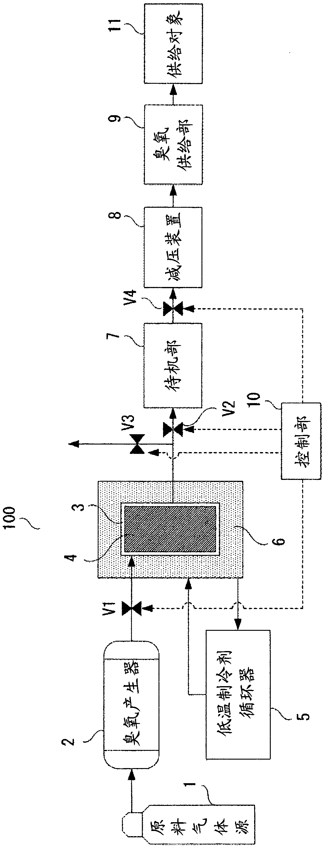
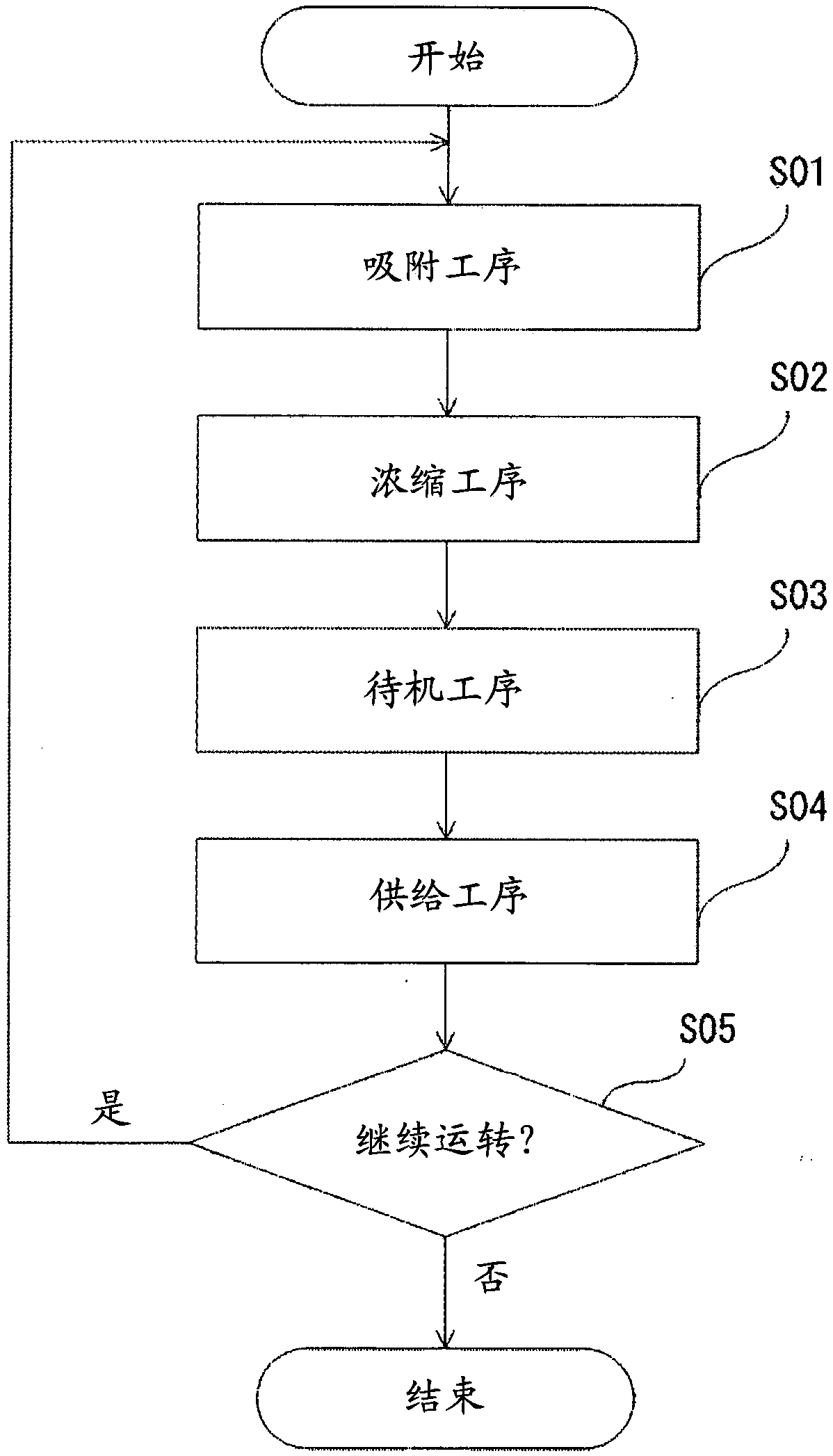
[0037] Embodiment 1 relates to an ozone supply device and an ozone supply method. The above-mentioned ozone supply device includes an ozone generator, an adsorption tower filled with an adsorbent inside, a standby unit for making ozonized gas stand by, a decompression device, and an ozone generator for supplying ozonized gas. A supply unit, a low-temperature refrigerant circulator for cooling the adsorbent, and a control unit for adsorbing the ozonated gas on the adsorbent and desorbing the ozonated gas adsorbed on the adsorbent to concentrate, the ozone supply method includes an adsorption step, Concentration process, standby process and supply process.
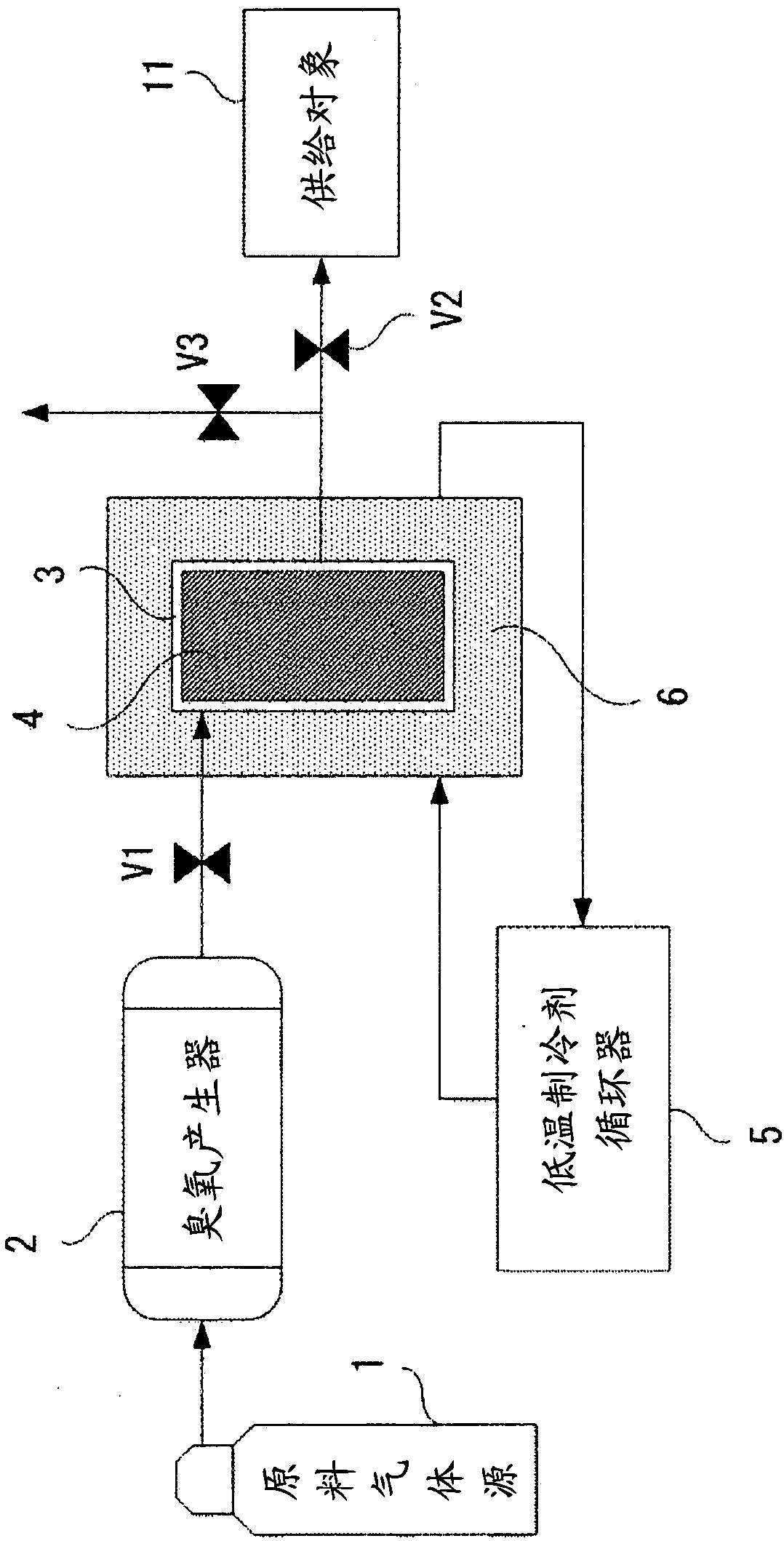
[0038] In the following, based on the system schematic diagram showing the structure of the ozone supply device, that is figure 1 , The flowchart of the ozone supply method is figure 2 , The explanatory diagram of the comparative example is image 3 , The schematic diagram of the process of the ozone supply device is Fi...
Embodiment approach 2
[0127] The ozone supply apparatus of Embodiment 2 adds a pressure gauge to the ozone supply apparatus 100 of Embodiment 1, and controls the pressure in the adsorption tower 3 and the standby part 7.
[0128] Hereinafter, based on a system schematic diagram showing the structure of the ozone supply device of Embodiment 2, that is Figure 10 , and the characteristic diagram showing the relationship between the pressure in the adsorption tower of the ozone supply device and the purity of ozone is Figure 11 , the ozone supply device of Embodiment 2 will be described centering on differences from Embodiment 1. exist Figure 10 , with Embodiment 1’s figure 1 The same or equivalent parts are denoted by the same reference numerals as in the first embodiment.
[0129] The basic structure of the ozone supply apparatus of Embodiment 2 is the same as that of the ozone supply apparatus 100 of Embodiment 1, but in the ozone supply apparatus 200, the pressure gauge 204 is provided in the...
Embodiment approach 3
[0137] The ozone supply apparatus of Embodiment 3 adds an ozone meter to the ozone supply apparatus 100 of Embodiment 1, and controls the ozone purity and ozone partial pressure in the adsorption tower 3 and the standby part 7.
[0138] Hereinafter, based on a system schematic diagram showing the structure of an ozone supply device according to Embodiment 3, Figure 12 , the ozone supply device of Embodiment 3 will be described centering on differences from Embodiment 1. exist Figure 12 , with Embodiment 1’s figure 1 The same or equivalent parts are denoted by the same reference numerals as in the first embodiment.
[0139] The basic structure of the ozone supply apparatus 300 of Embodiment 3 is the same as that of the ozone supply apparatus 100 of Embodiment 1, but in the ozone supply apparatus 300, the ozone meter 24 is provided in the rear stage of the adsorption tower 3.
[0140] The ozonometer 24 measures the ozone purity and ozone partial pressure in the adsorption t...
PUM
 Abstract
Description
Claims
Application Information
 - R&D
- Intellectual Property
- Life Sciences
- Materials
- Tech Scout
- Unparalleled Data Quality
- Higher Quality Content
- 60% Fewer Hallucinations
Browse by: Latest US Patents, China's latest patents, Technical Efficacy Thesaurus, Application Domain, Technology Topic, Popular Technical Reports.
© 2025 PatSnap. All rights reserved.Legal|Privacy policy|Modern Slavery Act Transparency Statement|Sitemap|About US| Contact US: help@patsnap.com