Supercharge Your Innovation With Domain-Expert AI Agents!

Single-roller high-pressure and high-frequency vibration roller grinding crusher

A high-pressure high-frequency, vibrating roller technology, applied in grain processing and other directions, can solve the problems of low crushing efficiency and short-term crushing blind area, and achieve the effect of improving grinding efficiency

Inactive Publication Date: 2018-09-04
ZAOZHUANG SNKSAN INTELLIGENT MACHINERY CO LTD
View PDF1 Cites 2 Cited by
  • Summary
  • Abstract
  • Description
  • Claims
  • Application Information

AI Technical Summary

Problems solved by technology

[0004] In order to solve the above problems, the patent application number CN201711126347.0 proposes a single-roll high-pressure high-frequency vibration roller mill crusher with simple structure, strong adaptability, reliable performance, large processing capacity and good crushing effect. However, this crusher The extrusion roller is driven by a high-frequency vibrator to act on the material on the extrusion plate, and is crushed through extrusion and the rotation of the extrusion roller, but there is still the defect of low crushing efficiency; at the same time, the extrusion of this crusher The pressure roller rotates clockwise, and the material is unloaded by using the friction of the extrusion roller rotation and the gravity of the material itself. When the extrusion roller is far away from the extrusion plate, there is a short-term crushing blind area. At this time, the material is directly crushed without being crushed. falling

Method used


Image

  • Single-roller high-pressure and high-frequency vibration roller grinding crusher
  • Single-roller high-pressure and high-frequency vibration roller grinding crusher
  • Single-roller high-pressure and high-frequency vibration roller grinding crusher

Examples


Embodiment Construction

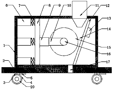
[0023] The technical solution of this patent will be further described in detail below in conjunction with specific embodiments.

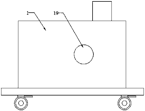
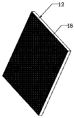
[0024] Embodiments of the present patent are described in detail below, examples of which are shown in the drawings, wherein the same or similar reference numerals designate the same or similar elements or elements having the same or similar functions throughout. The embodiments described below by referring to the figures are exemplary and are only used for explaining the patent, and should not be construed as limiting the patent.

[0025] In the description of this patent, it is to be understood that the terms "center", "upper", "lower", "front", "rear", "left", "right", "vertical", "horizontal", The orientation or positional relationship indicated by "top", "bottom", "inner", "outer", etc. is based on the orientation or positional relationship shown in the drawings, and is only for the convenience of describing this patent and simplifying the des...


PUM


Abstract

The invention provides a single-roller high-pressure and high-frequency vibration roller grinding crusher, and belongs to the technical field of crushing equipment. The single-roller high-pressure andhigh-frequency vibration roller grinding crusher comprises a box body, a bottom plate and moving devices. The box body is arranged above the bottom plate. The lower portion of the bottom plate is fixedly connected with the moving devices through four supporting plates. A feeding hopper is arranged on the upper right portion of the box body. A hydraulic drive device composed of multiple hydrauliccylinders is arranged on the left side in the box body. The right sides of the hydraulic cylinders are fixedly connected with a top plate through springs. The middle of the right side of the top plateis fixedly connected with a high-frequency vibration exciter. The right side of the high-frequency vibration exciter is connected with a connecting rod. The right end of the connecting rod is connected to a rotary shaft in a sleeving manner. An extrusion roller is welded to the rear end of the rotary shaft. Through protrusions, material grinding is finer and more uniform, and the grinding efficiency is improved. The extrusion roller rotating anticlockwise generates upward friction force to falling materials, the material falling speed can be reduced through the upward friction force, and thesituation that when the extrusion roller moves to the maximum position on the left side, the materials fall off without being ground, and consequently the grinding efficiency is reduced is avoided.

Description

technical field [0001] The invention relates to a crushing device, in particular to a single-roller high-pressure high-frequency vibration roller mill crusher. Background technique [0002] The application of high-pressure roller mills began in the 1980s. From the mid-1980s to the early 1990s, foreign high-pressure roller mills were mainly used in the cement industry and diamond mining industry, and were widely used. From the mid-1990s to the early 2000s, high-pressure roller mills gradually began to be used in the field of mineral processing. In recent years, with the gradual perfection and improvement of stud wear-resistant technology, and the output particle size of high-pressure roller mill can be less than 5mm, it is the key equipment for ore to achieve more crushing and less grinding, energy saving and consumption reduction, and it is constantly being used in the field of mineral processing. To expand the application, more and more mineral processing plants have adop...

Claims


Application Information

Patent Timeline
IPC IPC(8): B02C4/12B02C4/28B02C21/02B02C19/16
CPCB02C4/12B02C4/28B02C19/16B02C21/02B02C2021/023
Inventor 孙启祥马驰孙法虎
Owner ZAOZHUANG SNKSAN INTELLIGENT MACHINERY CO LTD
Features
  • R&D
  • Intellectual Property
  • Life Sciences
  • Materials
  • Tech Scout
  • Unparalleled Data Quality
  • Higher Quality Content
  • 60% Fewer Hallucinations
Learn More